Git Product home page Git Product logo

opencncpilot's Introduction

OpenCNCPilot

OpenCNCPilot is a GRBL compatible G-Code Sender.

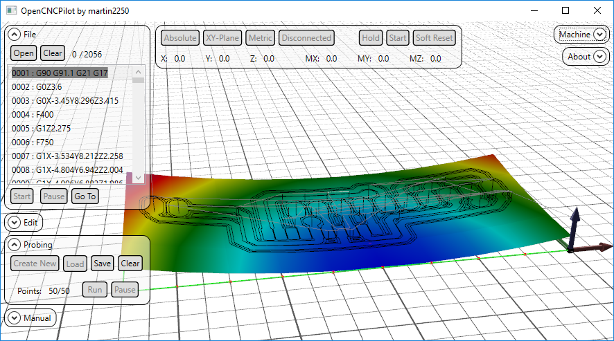
It's main feature is it's ability to probe user-defined areas for warpage and wrap the toolpath around the curved surface. This is especially useful for engraving metal surfaces with V-shaped cutters where any deviation in the Z-direction will result in wider or narrower traces, eg for isolation milling PCBs where warpage would result in broken or shorted traces.

Screenshot

It is written in C# and uses WPF for it's UI. Sadly this means that it will not run under linux as Mono does not support WPF. The 3D viewport is managed with HelixToolkit.

Here is a quick overview on YouTube https://www.youtube.com/watch?v=XDCu3cgOjCY

Installation

Install .NET 4.6, this has been the cause of at least 6 support requests so far.
Go to the Releases section and download the latest binaries (or compile it from source). Unzip all files to your hard drive and run "OpenCNCPilot.exe"

Make sure to use GRBL version 1.1f (later versions may work but are yet untested). Earlier versions (0.8, 0.9, 1.0) will NOT work! There are no workarounds, so you need to update your controller to use OpenCNCPilot.

Quick Start Guide

Before the first run, you have to select a Serial Port, the selector is hidden in the Settings menu that you can access in the "Machine" tab. Other than that you don't need to modify any settings.
Now you can connect to your machine.

Open gcode or height map files by dragging them into the window, or using the according buttons.

To create a new height map, open the "Probing" tab and click "Create New". You will be asked to enter the dimensions.
Be sure to enter the actual coordinates eg when your toolpath is in the negative X-direction, enter "-50" to "0" instead of "0" to "50". You can also use the "Size from GCode" button to fill in everything automatically. You will see a preview of the area and the individual points in the main window

To probe the area, set up your work coordinate system by going to your selected origin and using the "Zero (G10)" in the "Manual" tab, remember that this doesn't actually send the line, you can review it must send it manually. You can also use G92, but remember that G92 isn't permanent and will be lost after a reset.
Make sure to connect A5 of your Arduino to the tool and GND to your surface, and hit "Run".

OpenCNCPilot will now probe your board at the locations marked with a red dot and build the map from that data.

Once it's done probing the surface, hit the "Apply HeightMap" button in the "Edit" tab. Now you can run the code with the "Start" button in the "File" tab.

Manual Expressions

The 1.5 update adds an interpreter for mathematical expressions to use with manual send and macros. To use it, enter your expression in parentheses, like so: "G0 X(2*MX - 1)".

Available variables are:

  • MX, MY, MZ: machine position; WX, WY, WZ: work position
  • PMX, PMY, PMZ, PWX, PWY, PWZ: last probed position in machine/work coordinates
  • TLO: current tool length offset

the parentheses will be replaced with whatever the expression evaluates to. My Calculator library is used to evaluate the expressions.

Notes

The probing data is stored in an array of (double precision) floats, the intermediate values are obtained via bilinear interpolation between the four nearest points. All GCode commands whose length exceeds the GridSize are split up into sections smaller than the GridSize. This includes arcs.

In the input files, arcs can be defined via center (IJ) coordinates or by a radius (R). The output file will always use IJ notation, absolute coordinates and metric units. Both relative coordinates and imperial units are supported, but are converted to the aforementioned format.

Supported G-Codes:

  • G0, G1 linear motion
  • G2, G3 arc motion
  • G4 dwell
  • G20, G21 units
  • G90, G91 distance mode
  • S spindle speed
  • M M-codes

Donations

Since this project did get some attention, I'll include a donation button. Getting this application to a point where it's 'production-ready' took many days of non-stop work before and during the fist three semesters of my physics studies.
Please note that my programs will always be (ad-)free
paypal

opencncpilot's People

Contributors

eried avatar gonzalocargut avatar martin2250 avatar paciente8159 avatar

Stargazers

 avatar  avatar  avatar  avatar  avatar  avatar  avatar  avatar  avatar  avatar  avatar  avatar  avatar  avatar  avatar  avatar  avatar  avatar  avatar  avatar  avatar  avatar  avatar  avatar  avatar  avatar  avatar  avatar  avatar  avatar  avatar  avatar  avatar  avatar  avatar  avatar  avatar  avatar  avatar  avatar  avatar  avatar  avatar  avatar  avatar  avatar  avatar  avatar  avatar  avatar  avatar  avatar  avatar  avatar  avatar  avatar  avatar  avatar  avatar  avatar  avatar  avatar  avatar  avatar  avatar  avatar  avatar  avatar  avatar  avatar  avatar  avatar  avatar  avatar  avatar  avatar  avatar  avatar  avatar  avatar  avatar  avatar  avatar  avatar  avatar  avatar  avatar  avatar  avatar  avatar  avatar  avatar  avatar  avatar  avatar  avatar  avatar  avatar  avatar  avatar

Watchers

 avatar  avatar  avatar  avatar  avatar  avatar  avatar  avatar  avatar  avatar  avatar  avatar  avatar  avatar  avatar  avatar  avatar  avatar  avatar  avatar  avatar  avatar  avatar  avatar  avatar  avatar  avatar  avatar  avatar  avatar  avatar  avatar  avatar  avatar  avatar  avatar  avatar  avatar  avatar  avatar  avatar  avatar  avatar  avatar  avatar  avatar

opencncpilot's Issues

GRBL Version

Seems like this program only works with GRBL 0.9i and not GRBL 1.1.
Is there plans in the future to make one compatible with GRBL 1.1?

Return to zero.

Hi there,

I've noticed that, when the program finishes doing a tool pass it does not return to Zero and when I click the "return to zero" option, it only returns virtually but not mechanically, that is, it only returns in the software but not in my CNC. What am I missing? Is there any way to do this?

Cheers!

Problem with height calibration

I found a big problem with your software, while more test points I assign(for example each 3mm), more unstable the calibration becomes...sometimes the tool does not even touch the pcb when it is etching, it's like it calibrated it too high,... I cleaned my pcb very well before etching

20180301_184159

This i did with 2 mm test points spacing, this result I got about 5 times... if I set 5 mm it works reasonably well, but if I increments the accuracy decreasing the tests points spacing, that happens as the image.

Save probing grid settings

When iterating through sucessive probings, using different coordinates on the PCB, every time the settings have to be adjusted.

Question: Probing

What g-code cmd does it use to probe ? how is it dependent on port A5 ?

tool change command keeps job locked

Hi Martin,

another issue I stumbled over in my last project is tool change.
You already implemented the acceptance of tool change commands in the G-code file.

Normally, after stopping the batch for a tool change, you would move the tool to some offset (at least in Z direction), where you can fumble another bit into the drill holder.
That is not possible, all manual input is blocked when a batch is on the run, even when paused.
One can circumvent this by telling the G-code generator to move to a convenient Z coordinate before stopping.

But think further.
Changing the bit (having a normal clamp holder without known bit length for every bit) implies that one has to probe for Z zero with this new bit.
That can't likely be done at the given X/Y position, assuming that there has already been removed some material.
So we have to move X and Y as well to go to a known zero point and afterwards back to where we started with the tool change prcedure and can resume the batch.

Sounds complicated to me... and probably is :-)
Any ideas to that?

(did I already mention this problem earlier??? Don't know...)
Harald

Some questions/suggestions

Hi Martin,

Some Questions:

  1. I have just extended your code to allow import of standard .svg files to gcode.

image

Would such an addition be useful for you?
2. PC Boards are so cheap to order directly on line and the result is so much better than engraved from a cnc. What is your consideration(s) for the curvature map.?
3. I recently finished my cnc build and my first cut was just a .5mm pocket on the entire cutting surface with a 16mm flat bit. This immediately solved any curvature issues and I have a 100% flat wasteboard.
Why are you not able to address curvature with this approach?

I intend to further extend the svg import to allow selection of tools and depths via the colors of paths, Do you intend to add a Tool library to your project at any time?

Thanks for a great solution!

Kind Regards

VIRTUAL MACHINE MACBOOK

I have a virtual machine on the Mac, but I get an error and I can not run the program. Does anyone know how to fix it? Thnks

vector proccessing feature

sorry to open ticket for my question , actually I look for GUI interface for my GRBL board , I've find couple of good repo's for that matter however some of the only visualize and send gcode file to serial port and others only convert vector file to gcode, I was wondering if you have any plan to combine such feature in your repo and probably look at some other repo with missing feature
BR

file dialogs should remember last location

to open a file (G-code or hight map) a standard file open dialog is raised, I can navigate to the file location, select the file and leave the dialog with OK.
When I next will open this very file again, I again have to navigate to the file location.
It will be easier to handle if the program remebers the last folder and proposes this as new starting point.

Just my thoughts about user friedly experience :-)

Harald

question concerning the sources

Hi Martin,
is it ok to raise issues for every little question?
Is there perhaps another way to contact you?

I recently (some days ago) downloaded the sources to get hold on your latest changes and found a file "test.pfx" as part of the solution, but not the file itself.
To get the solution to compile I had to remove the file from the solution.
What's about that file? Seems not to be urgently needed...

Harald

Error message when opening an Estlcam V8 generated G-Code file

Hi Martin!
I use Estlcam V8 as preprocessor for converting DXF files into G-Code.
Sometimes OpenCNCPilot accepts those files, more often I get an error message like this:

grafik

The G-code in the given line is a commment:

(Projekt LOGO_Display_3D_V3_2)
(Erstellt mit Estlcam Version 8 Build 8,507)
(Laufzeit ca. 00:33:49 Stunden)

(Benoetigte Werkzeuge:)
(Fraeser 3,175)
(Fraeser 1mm)
G21
G90
G94
M03 S16000
G00 Z5.0000


(Nr. 1: Tasche raeumen: Ausschnitt 1)
G00 X83.8998 Y1.8700 Z5.0000
G00 Z0.5000
G01 Z-6.0000 F200 S16000
...

Line 15 is this one:
"(Nr. 1: Tasche raeumen: Ausschnitt 1)"

If I delete this line 15 the error moves to line 14, which is the empty line before
"G00 X83.8998 Y1.8700 Z5.0000"

That leads me to the guess, that the issued error line is one less than the real culprit.

But what is wrong with
"G00 X83.8998 Y1.8700 Z5.0000" ??

Do you have a hint? Or a solution? ;-)

Thanks
Harald

Apply HightMap discards spindel and timer commands

When applying height map to a g-code file:

(.../pcb-gcode-3.6.2.4/pcb-gcode.ulp)
(Copyright 2005 - 2012 by John Johnson)
(See readme.txt for licensing terms.)
(This file generated from the board:)
(.../Isolationsfräsen_Tests/Iso_1/Iso_1.brd)
(Current profile is .../pcb-gcode-3.6.2.4/profiles/generic.pp  )
(This file generated 10.03.2017 20:07)
(Settings from pcb-machine.h)
(spindle on time = 3.0000)
(  Tool Size)
(0.1000 )
(spindle speed = 30000.0000)
(tool change at 0.0000 0.0000 40.0000 )
(feed rate xy = F508.00 )
(feed rate z  = F254.00 )
(Z Axis Settings)
(  High     Up        Down     Drill)
(12.0000 	2.5400 	-0.1778 	-0.8128 )
(Settings from pcb-defaults.h)
(isolate min = 0.0254)
(isolate max = 0.5080)
(isolate step = 0.1270)
(Generated top outlines, top drill, bottom outlines, bottom drill, )
(Unit of measure: mm)
(Metric Mode)
G21
(Absolute Coordinates)
G90
S30000
G00 Z12.0000 
G00 X0.0000 Y0.0000 
M03
G04 P3.000000
G00 Z2.5400 
G00 X1.5551 Y1.8609 ....

the output is converted to:

G90 G91.1 G21 G17
G0Z12.019
G0
M3
G0Z2.559
G0X1.555Y1.861Z2.576 ....

"S30000" as well as "G04 P3.000000" is removed, the spindel doesn't start and has no time to spin up (ok, that doesn't matter either, but just to not forget about it... ;-)

Harald

(I'm sorry, I am not able to insert citations without beeing converted to word-wrap text. Any hints?)

Feedrate of 100 gets deleted when simplified

Just noticed this bug and I thought I might let you know. When you open up a gcode file with the feedrate set to 100 and simplify the file the feedrate setting gets deleted and grbl defaults to a very slow feedrate, which forces you to pause the job, enter the feedrate through the manual control box, and continue the job. I just tested it with a feedrate set to 101 and it does not get deleted by the simplifier.

image
image

spindle speed (g-code Sxxxx) doesn't result in correct speed setting at GRBL output

GRBL can set the spindle speed by issuing a PWM signal at a given pin.
The hi/lo percentage of the PWM signal is controlled by the S command in terms of 10th percent.
This implies, that the command S1000 results in 100% PWM duty cycle.

If your spindle turns 24000 rpm max and you want to adjust the speed to 16000 you have to set the S parameter in the g code manually to something about 666. Not so catchy.

It would be fine to have a direct dependency of the value behind the S command and the spindle speed (S12600 should result in 12600 rpm).
So you should implement a means of setting the factor for the given spindle controller in form of maximum speed for 100% PWM and then calculate the correct percentage value for the S value.

Just an idea :-)

OpenCNCPilot serial connecting error

error1
error2

Hi Martin,
I wanted to thank you for the beautiful project you made.
I already used your first version of the autoleveler program with GRBL.
I am writing to you because I have problems connecting to the OpenCNCPilot program.
When I select the serial port where I obviously have GRBL version 1.1f, the program returns the following error:
I tried connecting to other programs on the same serial port, for example universal gcode sender connects without any problems.
You could help me understand why OpenCNCPilot does not connect to the serial port.

Add option to single probe point

Hey, it would be good to have an option to make a single probe point.
I usually use that to set the Z to 0.
So probe until it actives the probe and then send the command to zero the Z axis.

Thanks!

OpenCNCPilot

Hey Martin

How hard would it be to make a version of the Open CNC Pilot for Mac OS X? because lots of people use Mac for use with CNC machines etc?

Cheers Benjamin

Connection problem

Good Day,
OpenCNCPilot installed on my win_7 PC.
GRBL 1.1 e installed on Arduino and working well with my CNC.
Problem:

Machine/setting : it allows the selection of com_6 port at 115200 baud_rate.
Connect : it says it is already connected.
Manual: I wrote : " G0 X15 " but all the buttons are NOT ACTIVE.
File/Open : I select a GRBL file created with Inkscape and working on the CNC: The program says " Method not found ... etc ".
Any direction to proceed please ?
Thanks
Ambro

wrong version number in GRBL 1.1f link

perhaps not worth to mention, but perhaps you should correct the text for the link to "GRBL 1.1f" on the download page

grafik

The link itself is fine, but I was starteled, when I read it for the first time, thought "wow, already a new version... what is wrong with 1.1f?"
Harald

Prob Fail

Hello everyone !
First of all, thank you to the developer(s) of OpenCNCPilot.
I have some errors but with the CNCPilote 1.3.1 and GRLB V1.1 it was solved.

But despite that, each time that I check " Aboart on probe fail" the program stops working.
It is the same thing when I click "run" for the probing map.
I've tried to put (force) the A5 pin to 5V (4.43V at rest) as 0V (to GRND) but it is the same thing.
I think it is the software... What do you think ?

Thank you !!

Parse Error

Got an error when reading in some gcode generated from Aspire for the Shapeoko 3,

capture

Part of Gcode:
T1
G17
G21
G0Z19.0754
G0X0.0000Y0.0000S16000M3
G0X12.3825Y12.3825Z19.0500
G0Z3.1750
G1Z-0.2540F635.0
G1X13.0175F762.0

I can fix it by removing the S and M commands, which I don't use.

stopped in the middle of a job

Hi Martin,
I am a complete beginner to cnc milling but i have been making PCBs for many years with the etching method, i,m 70 years young so have patience with me please.
I have been using your great software for a few weeks now and had fantastic results with my pcb milling, i am using your latest version of open cnc pilot and it all seemed to work ok until today.
I set up my Shapeoko 2 to mill a new pcb and probed the board, all ok so i started the milling but half way through the job it just stopped, no buttons had been pressed or anything. on the scrolling code in the bottom right hand corner of the screen i could see it was scrolling idle but had no idea why.
The all the buttons were as they should be, i repressed start a few times but nothing happened, in the end i just had to abbort the job. if you have any idea what had gone wrong i would be greatful for any advice you could give me.
Kind regards, Colin

Z axis movement slow when board used Imperial units

I haven't collected any evidence for this; but I original design my Eagle board layout using Imperial units. I ran it through GCODE then CNCPilot. The Autolevelling worked and I then used the modified .tap file with grblControl to etch the pcb. There was some positioning of the drill head, it started and then when responding to moving the tool to the board the movement was incredibly slow (like go to bed and come back the next day for one instruction!). This is just a guess but it seems you convert the .tap file measurements in Inches to mm and somehow don't convert the Z axis movement. Apologies if this is me screwing it up. When I go back to Eagle and use cm (mm) everything works fine.
I should add that when the probing is being done there are about a dozen errors thrown out on the screen for each sample point. These don't seem to affect the end result.

bug in displaying realtime feedrate?

Hello Martin,
Thank you for the amazing piece of software you created.I use OpenCNCPilot for encraving surfaces.
Love the Graphic presentation of the milling tracks. Also with 3d milling and many g-code lines.
Would it be possible to represent the processed tracks graphically different?
It would also be possible insert a easy prozesstimer? To know how long the milling job took.
The realtime feedrate display in status bar does not work for me. :( F: show only 0
Have to change something in the status report mask $=10 in grbl, currently 1?
Sorry for my bad english.
Stefan

more keyboard buttons for commands please

hello great job with this software. i have some requests if possible. 1 add option in setting to have all tabs unfolded at startup. 2 do option to hide the 3d grid too much gray my opinion :) 3. add mode shortcuts for commands. i use a Bluetooth gamepad connected to pc and mapped as keys with a free software. i have some morr keys which may be very useful to be used. for example change speed of jogging or probing or make origin or go to safe pozition, spindle on /off also a button to restore origin may help. thank you.

missing digits in file dialog

If the g-code file has more than 999 lines, there are digits cut off at the lines display just at the right side of the Clear button.

missing_digits

arranging macros in different order

Hi Martin,
I used the macros option really frequently when preparing the milling of my PCB. Very good idea!

Having entered some macros in a non plannend sequnce, I really quick came to the moment when I wished I have had thought a moment about the sequence and some grouping of my excellent crafted macros.

Is there a way to rearrange the order of the entered macros?
Some resemblance of grouping can be imitated by entering a macro with name "--------" and nothing to do in the body.

Harald

Spindle does not start and mapping does not work

Hi Martin,
you tool is wonderful, makes my little Chinese cnc work as a good cnc =)
It has been a couple week since I am having some troubles though.
The spindle sometimes start to spin and sometimes does not and these cause the tip to break.
I wonder If it is a problem of the setting of the software or I do something wrong with the .ulp pcb-gcode-setup on Eagle.
Another problem I am facing these last weeks is that even if I click on apply height map the tip does not etch because it is too far up with respect to the copper.
I hope you can help me.
I am running the software on windows and I have Grbl1.1
Thanks

OpenCNCpilot Freezes mid operation

I was using version 1.4.1 and ran into an issue with the attached file.
Default settings 115200 baud, 120 line buffer.
opencncpilot would randomly stop sending commands to grbl, with debug on, I can see grbl is still sending status.

If I am on a gcode command that includes feed rate, I can disconnect, then reconnect and continue. Unitl disconnect and connect is pressed, opencncpilot acts like it is not connected although the data from grbl is being seen.
I tried decreasing buffer, this did not help.

It is currently attached to arduino nano with ch340 chip. I will try with authentic ftdi arduino.

Any recommendations?
The program looks great and its simplicity is awesome.

Thanks,
Cody

Speed1.top.etch.tap.zip

Grbl Unlock and Origin Settings

As I understand it, the workflow is to setup your CNC (Shapeoko 3) with another application first, I use CNC by Cheton. I connect to my CNC and initialize it; Unlock, Home and set Work Zero. I then have to disconnect the COM Port so OpenCNCPilot can use it. I then open OpenCNCPilot and connect. I assume that I would then manually do an Unlock, Home and use the previous Work Zero before doing anything else.

Is this correct?

Thanks

Generating probe area with negative values does not work

I think I've found a bug while trying to generate a probe area.

Somehow the area does not take the first component of the X axis into consideration, unless you press the "Size from GCode" button. I tried it with both positive and negative values.

image
This is the initial probe are.

image
This is the probe area with the first component of the X axis set to 20. Notice that the probe area is still the same.

image
Same with first X point set to -20

image
"Size From GCode" somehow works

Best Regards

GRBL1.1.

Hello Martin
Bravo for this software
I can not load GRBL1.1.

I did a lot of research, I did several tests by modifying config.h and cpu_map.h but Arduino can not compile.
I am from Bordeaux, new in this field, I work with RAMPS 1.4 and Atmega2560.

Can you help me to find the solution?
Regards

Tooltip of buffer progress bar wrong?

Tooltip of the progress bar says, Bit 1 of $10 has to be set.
On my setup I have $10=0 and the progress bar works like a charm.
Perhaps a remainder from implemntation for GRBL 0.9xx?

Harald

GrblSettingsWindow

Hi Martin!
Super idea that settings window. One had to look up the meaning of those numbers every time when trying to change something, now you can read in plain text what's up with the parameters.

... but I miss the numbers ;-)
Would it be possible to write down the numbers as well, adjacent to the explanations, since we are used to set "$10=0", not knowing, that this parameter is "Status report options".

If you manage to add the dimension (mm, sec, steps, ...) behind the edit boxes, that would be even greater.
Just an idea.

Harald

GrblSettingsWindow (II)

Hi Martin!
When editing parameters in GRBL settings, you are able to step through the edit controls by entering <TAB>.
If you do so and change some parameters before applying, then the changes are visualized in the fading display zone, stating the transmission to GRBL.
Try that, close and reopen the dialog -> not all values are transmitted to GRBL.
Even worse: I didn't change the $10 parameter, left it on "0", but this param changed to "60".

Changing and applying the paramters one at a time, sending the changed param to GRBL after every edit operation works fine.

Do you run into race conditions when sending the changed params consecutively too fast?
Have in mind that saving something to EEPROM takes some time.
Do you wait for "ok" after sending a parameter or react on "stop" (or whatever GRBL issues when it has hickup)?

Harald

Connection

Hi Martin

When i went to connect to my Arduino Uno CNC shield with Open CNC Pilot i receive
'<idle|MPos:0.000,0.000,0.000|FS:0,0|Pn:XY>' in red text scrolling past on the App

~Ben

Save Modified Gcode

Is there a way to save the new gcode after the height map has been applied?

I would like to use other applications for the actual sending.

Thanks

Probe fail

Hi Martin,
I am new in the CNC world, so please be cautious.
I did install OpenCNC, running under Windows 10, GRBL Version 0.9i and I did make the brd file with Eagle.
The spindel (probe) is moving when I hit the RUN button. It stops with an alarm Probe Fail.
The GND is connected to the cnc shield GND, connected to the copper pcb. The probe is connected to the A5 pin of the CNC shield.
Please do you have any suggestions to solve this problem.
Thanks,
Jan

first coordinate of hight probing misses surface

I used probing for milling a printed circuit.
When I start probing on a new 40 by 30 mm grid, the sensor moves way too far into the PCB for the first probe.
Luckily I use spring probing contacts, so nothing bad occurs, but the resulting coordinate field has a kink at the front left edge (X Y zero).
hightmap1

Since you all made PCBs on your own and all works well, I suppose I did some mistake in setting up the process of probing?

Applying settings in menus via <Enter>

Most (or all?) dialogs have to be quitted with Accept (mouse click).
Many switches between keyboard and mouse.

In this context:
When opening a dialog it is best pratice to set the input focus to the first (only) input field.
In most of OpenCNCPilots dialogs there is no focus at all, it has to be set via mouse before you can enter values.

General discussion

as the title states.
please only use this thread for questions and discussion and open new feature requests for actual issues with OpenCNCPilot.

Martin

project gallery

Hi everyone,
I love seeing what you make with OpenCNCPilot, feel free to post pictures of the PCBs (or other projects) you make here.

Question on program structure

Hi Martin,
I already talked about my idea to attach a joystick to a second serial to issue jog commmands.

Can you please give me a clue where to start when trying the implementation on my own?
I added another tab in the settings dialog for the parameters of this second serial, but I'm unable to find e.g. the routine reacting on changing the COM port. No "on change" or similar.

I know, perhaps a too difficult task to kickstart someone into foreign code...
Harald

OpenCNCPilot Icon

Hi everybody,

I want to add an icon to OpenCNCPilot but I have no good ideas nor the artistic talent to draw one. If anybody has a good suggestion or wants to send one in, please do so :)
(svg file preferred)

Cheers!
Martin

Error message when clicking the connect button

I open the .exe file and then open the machine settings and select the com port to my Uno that has a CNC Shield with GRBL 0.9g installed on it. After closing the settings window I click on connect and the following error alert appears.
error

The OS is Win7 Home 64 bit
Thank You Dillard

Probing out of order

Hi !

First I'd like to thank you for the great work on this software. The interface is very nice and the job are done incredibly.

I made myself my machine, the main reason is to mill PCB's, so you can imagine how frustated I was when the result was terrible (without auto leveling), after using your software I was very happy with the result.

Please, forgive me if my question is too simple and I don't see the obvious reason or if there is some way to do it and I overlooked it.., But when I create a new height map, the probing points are visited out of order, this means the machine has to travel a lot between distant parts of the PCB.

There is any reason for the probing points not be visited in order to minimize the travel distance ? Or any way I could modify this on the current implementation ?

best regards from Brazil !

Alexandre

Recommend Projects

  • React photo React

    A declarative, efficient, and flexible JavaScript library for building user interfaces.

  • Vue.js photo Vue.js

    🖖 Vue.js is a progressive, incrementally-adoptable JavaScript framework for building UI on the web.

  • Typescript photo Typescript

    TypeScript is a superset of JavaScript that compiles to clean JavaScript output.

  • TensorFlow photo TensorFlow

    An Open Source Machine Learning Framework for Everyone

  • Django photo Django

    The Web framework for perfectionists with deadlines.

  • D3 photo D3

    Bring data to life with SVG, Canvas and HTML. 📊📈🎉

Recommend Topics

  • javascript

    JavaScript (JS) is a lightweight interpreted programming language with first-class functions.

  • web

    Some thing interesting about web. New door for the world.

  • server

    A server is a program made to process requests and deliver data to clients.

  • Machine learning

    Machine learning is a way of modeling and interpreting data that allows a piece of software to respond intelligently.

  • Game

    Some thing interesting about game, make everyone happy.

Recommend Org

  • Facebook photo Facebook

    We are working to build community through open source technology. NB: members must have two-factor auth.

  • Microsoft photo Microsoft

    Open source projects and samples from Microsoft.

  • Google photo Google

    Google ❤️ Open Source for everyone.

  • D3 photo D3

    Data-Driven Documents codes.