robbievanleeuwen / section-properties Goto Github PK
View Code? Open in Web Editor NEWAnalysis of an arbitrary cross-section in python using the finite element method.
Home Page: https://sectionproperties.rtfd.io
License: MIT License
Analysis of an arbitrary cross-section in python using the finite element method.
Home Page: https://sectionproperties.rtfd.io
License: MIT License


![dependabot[bot] avatar](https://avatars.githubusercontent.com/in/29110?v=4 "dependabot[bot]")


Describe the bug
When applying forces to a composite section with dissimilar materials, apparently erroneous stress are calculated. I am not sure yet what is causing this. The input geometry into the mesh seems fully correct and the mesh seems to also be correct. However, when an axial force is applied, the results are obviously incorrect. This does not happen when a single material is applied to both sections.
To Reproduce
See below gist:
https://gist.github.com/connorferster/6cbb131fe1b26124aae24d3e61bec980
Expected behaviour
Applied axial load should create a uniform stress corresponding to each material.
Desktop (please complete the following information):
@robbievanleeuwen, have you seen this sort of thing before in your earlier development?
It would be great to have a way to refer to the internal area of a hollow section, for things like heat / fluid flow, or buoyancy.
I've played around with a qhull on the mesh points, using shapely properties but for very thing sections nothing is reliable after an hour or so of play.
I think the best solution would be for the handful of hollow cross sections in the primitives in this library to define the 'holes' parameter of the meshpy interface, and then the areas could be returned with the same resolution as the physical mesh would.
BTW this library is integrating very nicely with the fea solver at https://github.com/JWock82/PyNite :)
Describe the bug
When creating custom cross-sections, and carrying out a clean_geometry() step, as recommended, small cross-sections are failing upon initialisation.
To Reproduce
Minimum bug example below
from sectionproperties.pre.sections import CustomSection
from sectionproperties.analysis.cross_section import CrossSection

def make_rectangle(width, height):
    points = [[-width/2, -height/2], [width/2, -height/2], [width/2, height/2],
              [-width/2, height/2]]
    facets = [[0, 1], [1, 2], [2,3], [3, 0]]
    return points, facets

def test_rectangle(width, height):
    points, facets = make_rectangle(width, height)

    geometry = CustomSection(points, facets, [], [[0, 0]])
    mesh_size = min([width, height])/2

    # This where the geometry is altered unexpectedly
    geometry.clean_geometry(verbose=True)

    mesh = geometry.create_mesh([mesh_size])
    section = CrossSection(geometry, mesh)

for w, h in zip([100, 10, 1, 0.1, 0.01, 0.001], [200, 20, 2, 0.2, 0.02, 0.002]):
    print('width: ', w, 'height: ', h)
    test_rectangle(w, h)
The above example fails relatively cryptically when we get to a small-ish rectangle, see traceback below:
width:  100 height:  200
width:  10 height:  20
width:  1 height:  2
width:  0.1 height:  0.2
width:  0.01 height:  0.02
Removed overlapping facets... Rebuilt with points: [0, 1]
Removed overlapping facets... Rebuilt with points: [1, 2]
Removed unused point 3
Traceback (most recent call last):

  File "<ipython-input-6-b7482b36466d>", line 21, in <module>
    test_rectangle(w, h)

  File "<ipython-input-6-b7482b36466d>", line 17, in test_rectangle
    section = CrossSection(geometry, mesh)

  File "C:\Anaconda3\lib\site-packages\sectionproperties\analysis\cross_section.py", line 210, in __init__
    init()

  File "C:\Anaconda3\lib\site-packages\sectionproperties\analysis\cross_section.py", line 117, in init
    elements[:, [3, 4, 5]] = elements[:, [5, 3, 4]]

IndexError: too many indices for array
Expected behavior
(The above error can be avoided by leaving out the geometry.clean_geometry() stage.)
I would expect the clean_geometry() stage to work correctly regardless of size (within reason).
Solution ideas:
clean_geometry is not recommended for small cross-sections, then maybe an error or warning could be raised when a mesh has len(elements) == 0 (as is the case following clean_geometry(), which causes the above IndexError).Desktop (please complete the following information):
Additional context
Stumbled across this repo when trying to calculate section properties myself. Ran a simple existing test battery to check FE cross-section properties with analytical values. In doing so, came across this issue.
Big thanks for all the good work, very helpful, will be using in future.
Describe the bug
Hi Robbie
I've been playing around with how merging sections works and noted a few odd things happening that may either be bugs or simply limitations in the code or the way geometry can be merged that might need further investigation or at a the very least some additional coverage in the documentation if these are limitations.
Merging two geometries where they are touching or overlapping has mixed effects on the mesh generated. API documentation seems to only briefly discuss/note that overlapping geometries can be merged and cleaning the geometry will attempt to fix any issues with the mesh. I have noted in testing some scenarios that the mesh seems to be created but seems to bug out a bit and assume this is not intended!
Consider the following 4 scenarios which might cover practical use cases for generating merged sections to demonstrate the varying results in the mesh being generated:-


To Reproduce
Run the code below to demonstrate all 4 scenarios:
import sectionproperties.pre.sections as sections
from sectionproperties.analysis.cross_section import CrossSection

# Scenario 1 - just touching, assume this is intended behaviour regarding meshing
geometry1 = sections.AngleSection(d=150, b=100, t=8, r_r=12, r_t=5, n_r=16, shift=[230, 200])
geometry1.rotate_section(angle=180, rot_point=[230, 200])
geometry2 = sections.ISection(d=250, b=250, t_f=20, t_w=10, r=10, n_r=10)
geometry = sections.MergedSection([geometry1, geometry2])
geometry.clean_geometry(verbose=True)
mesh = geometry.create_mesh(mesh_sizes=[5, 5])
section = CrossSection(geometry, mesh)
section.display_mesh_info()
section.plot_mesh()

# Scenario 2 - slightly overlapping, assume this is the intended behaviour (provided control point is not in the overlapped region)
geometry1 = sections.AngleSection(d=150, b=100, t=8, r_r=12, r_t=5, n_r=16, shift=[223, 200])
geometry1.rotate_section(angle=180, rot_point=[223, 200])
geometry2 = sections.ISection(d=250, b=250, t_f=20, t_w=10, r=10, n_r=10)
geometry = sections.MergedSection([geometry1, geometry2])
geometry.clean_geometry(verbose=True)
mesh = geometry.create_mesh(mesh_sizes=[5, 5])
section = CrossSection(geometry, mesh)
section.display_mesh_info()
section.plot_mesh()

# Scenario 3 - two geometries completely overlapping, mesh only generated correctly within the regions with the control points?
geometry1 = sections.AngleSection(d=150, b=100, t=8, r_r=12, r_t=5, n_r=16, shift=[150, 200])
geometry1.rotate_section(angle=180, rot_point=[150, 200])
geometry2 = sections.ISection(d=250, b=250, t_f=20, t_w=10, r=10, n_r=10)
geometry = sections.MergedSection([geometry1, geometry2])
geometry.clean_geometry(verbose=True)
mesh = geometry.create_mesh(mesh_sizes=[5, 5])
section = CrossSection(geometry, mesh)
section.display_mesh_info()
section.plot_mesh()

# Scenario 4 - just touching but formation of a closed region, as no way to recognise the formation of the 'hole'?
geometry1 = sections.AngleSection(d=150, b=100, t=8, r_r=12, r_t=5, n_r=16, shift=[230, 170])
geometry1.rotate_section(angle=180, rot_point=[230, 170])
geometry2 = sections.ISection(d=250, b=250, t_f=20, t_w=10, r=10, n_r=10)
geometry = sections.MergedSection([geometry1, geometry2])
geometry.clean_geometry(verbose=True)
mesh = geometry.create_mesh(mesh_sizes=[5, 5])
section = CrossSection(geometry, mesh)
section.display_mesh_info()
section.plot_mesh()
Expected behavior
Some way of accounting for these scenarios without having to resort to defining custom sections (in the case of scenario 4) or more geometry elements (in the case of scenario 3)?
Or outline any limitations in the geometry merging method in the documentation?
Desktop (please complete the following information):
Many thanks!
Is your feature request related to a problem? Please describe.
No
Describe the solution you'd like
Switch at least the plot_centroids method to return the fig,ax objects so they can be properly saved, regardless of execution method.
Describe alternatives you've considered
I've tried implementing a plt.savefig(name) command after calling xsect.plot_centroids(). This will work with pause=False if executed on the command line, however if executed somewhere like a Jupyter notebook, the "current figure" that plt.savefig() grabs is blank (even if pause is True). Some users are getting no plots while I'm getting correct plots. Online users always recommend saving prior to showing, or using the plt.gcf() to return a Figure object for referencing later.
This should be a simple fix by returning fig,ax in the plotting methods. Then, the figure is stored directly in memory and can be addressed by python to fig.savefig() instead.
It may break some existing implementations, if returned objects are not expected. That's why I wanted to bring up an issue rather than jumping straight into a new PR.
Additional context
An object oriented approach with matplotlib is better, in my opinion, than the "default" plt.plot and plt.show. It allows more exact control. Am I missing something obvious?
Originally posted by Spectre5 February 22, 2021
Since ~2018, PyPI accepts README files in markdown. Is there a specific reason that we still need this RST version or the README then, or can we drop it in favor of only having the markdown one?
See here
Interestingly, the setup.py file already uses long_description_content_type='text/markdown' even though the readme function reads the reStructuredText version: with open('README_pypi.rst') as f: - which I'm slightly surprised even works. Perhaps if PyPI automatically recognizes that the description is in RST then it just ignores the value in long_description_content_type?
Remove README_pypi.rst with v2 release and hope PyPI likes images in markdown files!
Describe the bug
Empty legend box appearing in stress plots.
To Reproduce
import sectionproperties.pre.sections as sections
from sectionproperties.analysis.cross_section import Section

geometry = sections.angle_section(d=150, b=90, t=12, r_r=10, r_t=5, n_r=8)
geometry.create_mesh(mesh_sizes=[20])
section = Section(geometry)

section.calculate_geometric_properties()
section.calculate_warping_properties()
stress_post = section.calculate_stress(N=10e3)

stress_post.plot_stress_n_zz()
Expected behavior
Legend box removed.
Describe the bug
Under certain conditions, the CompoundGeometry mesh creation step (geometry.create_mesh) is failing.
To Reproduce
import sectionproperties.pre.sections as sections
from sectionproperties.analysis.cross_section import Section

s1 = sections.rectangular_section(1,1)
s2 = sections.rectangular_section(0.5,0.5).shift_section(1,0.25)

geometry = sections.CompoundGeometry([s1,s2])
geometry = geometry.rotate_section(angle=30, rot_point='center')

geometry.plot_geometry()
geometry.create_mesh(mesh_sizes=[0.2, 0.1])
section = Section(geometry)
section.display_mesh_info()
triangle.build produces errors in geometry.create_mesh(mesh_sizes=[0.2, 0.1]):
Internal error in segmentintersection():
  Topological inconsistency after splitting a segment.
  Please report this bug to [email protected]
  Include the message above, your input data set, and the exact
    command line you used to run Triangle.
In more extreme cases such as example_mirr_rot.py (after updating to run with v2) the process crashes.
Interestingly if the rotation step is either 0, 90, 180, ... the meshing is successful. For example,
import sectionproperties.pre.sections as sections
from sectionproperties.analysis.cross_section import Section

s1 = sections.rectangular_section(1,1)
s2 = sections.rectangular_section(0.5,0.5).shift_section(1,0.25)

geometry = sections.CompoundGeometry([s1,s2])
geometry = geometry.rotate_section(angle=90, rot_point='center')

geometry.plot_geometry()
geometry.create_mesh(mesh_sizes=[0.2, 0.1])
section = Section(geometry)
section.display_mesh_info()
Mesh Statistics:
--48 nodes
--17 elements
--2 regions
Expected behaviour
Meshing step completing.
Additional context
After some investigation, I think it is because the triangle is having a hard time with the facets:
import sectionproperties.pre.sections as sections
from sectionproperties.analysis.cross_section import Section

s1 = sections.rectangular_section(1,1)
s2 = sections.rectangular_section(0.5,0.5).shift_section(1,0.25)

geometry = sections.CompoundGeometry([s1,s2])
print(f"points: {geometry.points}")
print(f"facets: {geometry.facets}")
points: [[0.0, 0.0], [1.0, 0.0], [1.0, 1.0], [0.0, 1.0], [1.0, 0.25], [1.5, 0.25], [1.5, 0.75], [1.0, 0.75]]
facets: [[0, 1], [1, 2], [2, 3], [3, 0], [4, 5], [5, 6], [6, 7], [7, 4]]
These are the facets of the individual geometries and I think the meshing would prefer the combined shape facets:
points: [[0.0, 0.0], [1.0, 0.0], [1.0, 1.0], [0.0, 1.0], [1.0, 0.25], [1.5, 0.25], [1.5, 0.75], [1.0, 0.75]]
facets: [[0, 1], [1, 4], [4, 7], [7, 2], [2, 3], [3, 0], [4, 5], [5, 6], [6, 7], [7, 4]]
So:
import sectionproperties.pre.sections as sections
from sectionproperties.analysis.cross_section import Section

s1 = sections.rectangular_section(1,1)
s2 = sections.rectangular_section(0.5,0.5).shift_section(1,0.25)

geometry = sections.CompoundGeometry([s1,s2])
geometry_aug = sections.CompoundGeometry.from_points(
    geometry.points,
    [[0, 1], [1, 4], [4, 7], [7, 2], [2, 3], [3, 0], [4, 5], [5, 6], [6, 7], [7, 4]],
    geometry.holes,
    geometry.control_points
)
geometry_aug = geometry_aug.rotate_section(angle=30, rot_point='center')

geometry_aug.plot_geometry()
geometry_aug.create_mesh(mesh_sizes=[0.2, 0.1])
section = Section(geometry_aug)
section.display_mesh_info()
Mesh Statistics:
--52 nodes
--19 elements
--2 regions
Describe the bug
analysis.cross_section.calculate_frame_properties is printing solver timing information to the console, when time_info is False.
To Reproduce
import sectionproperties.pre.sections as sections
from sectionproperties.pre.pre import Material
from sectionproperties.analysis.cross_section import Section

steel = Material(
    name='Steel', elastic_modulus=200e3, poissons_ratio=0.3, yield_strength=250,
    color='grey'
)
timber = Material(
    name='Timber', elastic_modulus=8e3, poissons_ratio=0.35, yield_strength=20,
    color='burlywood'
)

geom_steel = sections.rectangular_section(d=50, b=50, material=steel)
geom_timber = sections.rectangular_section(d=50, b=50, material=timber)
geometry = geom_timber.align_to(geom_steel, on="right") + geom_steel
geometry.create_mesh(mesh_sizes=[10, 5])

section = Section(geometry)
print(f"time_info: {section.time_info}")
(area, ixx, iyy, ixy, j, phi) = section.calculate_frame_properties()
Console:
>>> time_info: False
>>> --Initialising the Section class...
>>> ----completed in 0.059121 seconds---
Expected behaviour
>>> time_info: False
I'm having trouble installing meshpy on a linux mint machine with Python 3.6.9, and ultimately found this closed issue on their github page. In there it says:
Unfortunately, Python 3+ will not be supported for meshpy. @jeffmahler
Since this conflicts with section-properties' Python 3.5+ requirement, maybe consider switching to triangle instead? It looks like it uses the same underlying mesh library.
Is your feature request related to a problem? Please describe.
Often for steel in piles or marine environments you are required to assess the section properties of a section after some defined section loss from the perimeter. Like say applying an annual corrosion loss from exposed surfaces multiplied by a number of years.
Describe the solution you'd like
A means of taking an original section and an additional parameter of a surface thickness loss and applying this loss of section to the external perimeter before creating the geometry and mesh.
For an I section for example altering within a pre-processing procedure that reduces the section inputs as follows (C = surface thickness loss) prior to creating the geometry:-
d = d - 2C
b = b - 2C
t_f = t_f - 2C
t_w = t_w - 2C
r = r + 2C
etc... for other shapes
Fairly easy to do in your own pre-processing code, but though it might be a nice addition to your programme for in built sections at least (and may even be able to be generalised for custom shapes). Would allow for looping through the properties over a timeframe to plot loss of capacity for example, useful for determining remaining life perhaps (may make a good advanced example similar to the others that you currently have).
Could also allow you to plot corroded section geometry plot against original on same plot (perhaps different coloured line or something)?
Describe alternatives you've considered
Do it in my own custom pre-processing code, adjusting section geometry inputs before creating reduced section geometry.
Thank you for this amazing package. I am not sure whether this is seen in the calculations and an option exists for in the API or not. But this is a case I have faced and results in irregular values for second moments and shear point coordinates.
Normally we introduce the points on the boundary of a Custom Section using some coordinates. The origin of the coordinate system may not be located on the center of the gravity or rigidity of the cross section (CR). For instance, the (0,0) may be located on the far left point of the cross section. This causes the second moment values to be far higher than those calculated while the origin of the system is considered to be on the CR of the cross section.
This may not be a huge problem when we are doing FEM analysis but in engineering control problems, this is very important specifically when we are using the API to check cross section with the specifications of a standard. We need most of the cross section properties to be calculated while the (0,0) and origin of the coordinate system is set to be on the centroid of the cross section and I am afraid I can not find any relevant option or API code to do so.
Would you mind; if such an option exists please let me know and if it is not seen, some options probably be added to the API to make the package more usable by such engineers?
Thank you
Just a general thought also as a suggestion for another advanced example demonstrating calculation efficiency:
I think it would be good to have an example showing for an I section that going to a finer mesh over the entire section isn't entirely warranted for accuracy, using more points around the curve for the root radii drives the mesh smaller in these regions and this results in accuracy where its needed and a much faster calculation overall for the same overall accuracy in the properties. Sort of similar to the example of calculating J with mesh size vs time, I think if you changed the points around the curved portions at a coarse mesh size you will see the same accuracy but much faster calculation time for the same problem!
EDIT Actually just qualifying that this might depend on what property you are calculating/interested in, certainly true for some properties.
Is your feature request related to a problem? Please describe.
No
Describe the solution you'd like
Switch at least the plot_centroids method to return the fig,ax objects so they can be properly saved, regardless of execution method.
Describe alternatives you've considered
I've tried implementing a plt.savefig(name) command after calling xsect.plot_centroids(). This will work with pause=False if executed on the command line, however if executed somewhere like a Jupyter notebook, the "current figure" that plt.savefig() grabs is blank (even if pause is True). Some users are getting no plots while I'm getting correct plots. Online users always recommend saving prior to showing, or using the plt.gcf() to return a Figure object for referencing later.
This should be a simple fix by returning fig,ax in the plotting methods. Then, the figure is stored directly in memory and can be addressed by python to fig.savefig() instead.
It may break some existing implementations, if returned objects are not expected. That's why I wanted to bring up an issue rather than jumping straight into a new PR.
Additional context
An object oriented approach with matplotlib is better, in my opinion, than the "default" plt.plot and plt.show. It allows more exact control. Am I missing something obvious?
Describe the bug
Docs not clear with relation to how properties are reported when material properties are used - even if only one material is used!
Describe the bug
There is an issue with CompoundGeometry.rotate_section where under the default parameters (rot_point = 'center') the individual geometries rotate about their own centers.
To Reproduce
import sectionproperties.pre.sections as sections
import matplotlib.pyplot as plt

a = 1
b = 2
t = 0.1

points = [[-t/2, -2*a], [t/2, -2*a], [t/2, -t/2], [a, -t/2], [a, t/2],
          [-t/2, t/2], [-b/2, -2*a], [b/2, -2*a], [b/2, -2*a-t],
          [-b/2, -2*a-t]]
facets = [[0, 1], [1, 2], [2, 3], [3, 4], [4, 5], [5, 0], [6, 7], [7, 8],
          [8, 9], [9, 6]]
holes = []
control_points = [[0, 0], [0, -2*a-t/2]]

geometry = sections.CompoundGeometry.from_points(points, facets, holes, control_points)

fig, (ax1,ax2) = plt.subplots(2)
geometry.plot_geometry(ax=ax1)
geometry = geometry.rotate_section(angle=30, rot_point='center')
geometry.plot_geometry(ax=ax2)
plt.show()
Expected behavior
That the section rotates about the compound geometries center.
Describe the bug
Hi Robbie
With close geometry coordinates being created followed by a clean_geometry, I've noted its possible for the code to get in what appears to be an infinite loop.
To Reproduce
Steps to reproduce the behavior with a small r_out applied and verbose=True with the CeeSection class. You can see it just keeps revisiting the same points during the clean geometry operation:-
import sectionproperties.pre.sections as sections
from sectionproperties.analysis.cross_section import CrossSection

# geometry of example channel
t = 1.16
d = 150
b = 40
l = 15
r_out = .1
n_r = 5

# create 2 channels, mirror second channel
channel1 = sections.CeeSection(d=d, b=b, l=l, t=t, r_out=(r_out), n_r=n_r)
channel2 = sections.CeeSection(d=d, b=b, l=l, t=t, r_out=(r_out), n_r=n_r)
channel2.mirror_section(axis='y', mirror_point=[0, 0])

# merge the two channels into a single section
geometry = sections.MergedSection([channel1, channel2])

# clean the geometry
geometry.clean_geometry(verbose=True)

Expected behavior
Some way of detecting whatever scenario results in the looping, and either raising an exception or handling it in some way.
Desktop (please complete the following information):
Meshpy creates a lot of issues for users - will triangle work?
Is your feature request related to a problem? Please describe.
When material properties are defined, some of the outputs are changed within .display_results() to output as E*xx and G*xx. To work back to the base property value (like back calculating I_xx from E*I_xx) it would be useful to have the material properties that were defined for the analysis to be output for future reference with the .display_results() command (otherwise its sort of hidden away in the code and isn't too evident from the output what was assumed).
Possibly also outputting yield strength + other material parameters like any modular ratio/Poisson ratio that might need to be applied or has been used in the analysis?
It's also not clear to me how these outputs with material properties applied are to be read when multiple materials are defined, I would assume the properties are transformed for one of the materials (but which one?), its not something that I can find in the API documentation or covered in the outputs and I think this might need further clarification.
An additional thing that comes to mind regarding materials is the bulk density for a given material, and hence weight/m could be calculated and reported.
Describe the solution you'd like
Some way of knowing what material the transformed section properties are being output in if some of the section has been scaled/transformed by modular ratios.
Describe alternatives you've considered
Possibly forego the multiplication with E/G/fy and just output these values and state which material the (composite) properties are based on.
I would also maybe consider a warning of sorts in the documentation that while you are calculating the plastic section modulus, that for design purposes in some codes local slenderness requirements may dictate that the actual section modulus to be used is lower due to use of effective section moduli which account for reductions in capacity due to local buckling of plate elements (i..e compact/non-compact/slender sections in NZS3404/AS4100 or Class 1/2/3/4 sections in Eurocodes).
Possibly also consider having an option on which material you would like the properties to be output based on to add a level of control on the desired output material properties (i.e. for a timber beam being strengthened with a steel plate it might be more useful to output properties in terms of the timber material, but for a composite steel beam with concrete slab the properties might be more normal to output in terms of steel materials).
Additional context
Thanks for adding in the other requests I had!
Is your feature request related to a problem? Please describe.
No
Describe the solution you'd like
Switch at least the plot_centroids method to return the fig,ax objects so they can be properly saved and/or modified, regardless of execution method.
Describe alternatives you've considered
I've tried implementing a plt.savefig(name) command after calling xsect.plot_centroids(). This will work with pause=False if executed on the command line, however if executed somewhere like a Jupyter notebook, the "current figure" that plt.savefig() grabs is blank (even if pause is True). Some users are getting no plots while I'm getting correct plots. Online users always recommend saving prior to showing, or using the plt.gcf() to return a Figure object for referencing later.
This should be a simple fix by returning fig,ax in the plotting methods. Then, the figure is stored directly in memory and can be addressed by python to fig.savefig() instead.
It may break some existing implementations, if returned objects are not expected. That's why I wanted to bring up an issue rather than jumping straight into a new PR.
Additional context
An object oriented approach with matplotlib is better, in my opinion, than the "default" plt.plot and plt.show. It allows more exact control. Am I missing something obvious?
Describe the bug
In the following code I would expect the plastic centroid to be at the origin (0, 0) and align with the elastic centroid. Yet it is reporting the plastic centroid below the origin. Section geometry centroid is shifted to 0,0 position.
Also, the horizontal principal axis is shown correctly at y=0, but the principal plastic axis centroid is not, being drawn below y=0.
The reported results agree with the plot in so far as the plastic centroid is not at 0,0 point.
Is this possibly a bug or maybe I'm missing something obvious here?
To Reproduce
Run code below and observe results
import sectionproperties.pre.sections as sections
from sectionproperties.analysis.cross_section import CrossSection

mesh_area = 25  # max mesh size

d = 612  # I section depth
b_f = 229  # I-section flange width
t_f = 19.6  # I-section flange thickness
t_w = 11.9  # I-section web thickness
r_1 = 14  # I-section root radii
n_r = 50  # number of points considered around root radii

d_p = 650  # strengthening plate depth
b_p = 12  # strengthening plate thickness

# create constituent geometry
geometry1 = sections.ISection(d=d, b=b_f, t_f=t_f, t_w=t_w, r=r_1, n_r=n_r, shift=[-b_f / 2, -d / 2])
geometry2 = sections.RectangularSection(d=d_p, b=b_p, shift=[-b_f / 2 - b_p, -d_p / 2])
geometry3 = sections.RectangularSection(d=d_p, b=b_p, shift=[b_f / 2, -d_p / 2])

# create merged section
geometry = sections.MergedSection([geometry1, geometry2, geometry3])

# add holes
geometry.add_hole([-b_f / 2, 0])
geometry.add_hole([b_f / 2, 0])

# create mesh
mesh = geometry.create_mesh(mesh_sizes=[mesh_area, mesh_area, mesh_area])

# clean geometry
geometry.clean_geometry(verbose=True)

# create section
section = CrossSection(geometry, mesh)

# calculate results
section.calculate_geometric_properties()
section.calculate_plastic_properties()
section.calculate_warping_properties()

# plot results
section.plot_mesh()
section.plot_centroids()

# display all results
# check https://sectionproperties.readthedocs.io/en/latest/rst/post.html for definitions
section.display_results(fmt='.3f')

# this will specifically display torsion and warping constants
J = section.get_j()
I_w = section.get_gamma()
print(f'J = {J}')
print(f'I_w = {I_w}')
Expected behaviour
For doubly symmetric section plastic and elastic centroid should align?
Screenshots
Note how principal plastic axis centroid does not align with the principal axes, and plastic centroid is shown below elastic centroid:-

Additional context
Using latest version 1.0.7
Is your feature request related to a problem? Please describe.
Am I missing something, or is there no version attribute/variable that one can easily call for this library?
Describe the solution you'd like
import sectionproperties as sp
print(f'SectionProperties Version: {sp.__version__}')
The above code will result, if a __version__ = '1.0.8' line is added to the overall init.py file (sectionproperties > init.py)
Additionally, your setup.py file and docs can reference this value, instead of manually updating them all for each release.
Describe alternatives you've considered
Some other python libraries use a version module. Not sure what the real purpose is of these, but I think a simple __version__ attribute for the library will suffice for basic checks.
Additional context
The reason for this consideration is to provide a user with a way to document what version of the library was used when performing an analysis. For engineering analysis, I typically like to log all library versions at the top, just so I can be sure I know how to repeat my results. As we start looking at overhauls to pre-, post-, testing suites, and meshing algorithms, this could be even more useful, and the change seems minor to me with no drawbacks.
Your thoughts, robbie? It's a simple change, but I could put in a PR for you to review? I'm trying to learn all the shapely and testing stuff along with the great work connor's doing, and I just noticed this while setting up. :)
Originally posted by Spectre5 February 12, 2021
@robbievanleeuwen what are you thoughts on switching from travis CI to the native github actions? After we add some lint/code quality checks to the repository, I'll follow up with another PR to add those checks to the CI pipeline. Travis is fine, I'm just more familiar with github actions. I'm mostly curious if there is a specific reason you're using travis instead?
I wanted to start a singular thread for all contributors to weigh in on our testing approach. I've been reading up on pytest, and remembered hypothesis(corrected, thank you Spectre!) as an additional library we could use. I apologize if none of this is really necessary, I just had thoughts and I wanted to write them down to try and help out. 😃
Firstly, it would benefit us to discuss timing. With #42 currently in progress (and looking good) it would likely mean a major version increment in sectionproperties. Do you want to wait until shapely is fully incorporated to begin developing tests? If we don't wait, do we progressively roll out testing, or lump it all in one release?
I'm completely inexperienced with software testing, so please weigh in if you know better! I don't even really know how a user could easily run our tests, after they're pushed with a release (or how to setup TravisCI to do it). However, I envision a two-fold approach to sectionproperties testing:
Functionality - The library needs to work for at least a majority of cases in which it could be used. If edge cases exist that cause unexpected behavior, they should be known. This is where hypothesis seems valuable, and from my reading this approach seems to be typically what people mean when they're talking about software testing.
Accuracy - Since this library performs engineering calculations, it should have some manner of proving its accuracy. Obviously each analyst who uses it is responsible for their own projects and calculations, but having a high level of confidence that the software can produce correct results, given the correct inputs, will be a boon to all users. This I see as setting up tests on known problems from academia, experimental results, and publications. It doesn't necessarily fall into an edge case that might break the code. We don't need to test and validate every step of the FE process, that would be frivolous, but comparing to examples in a textbook seems feasible (I don't have a copy of Pilkey, I'll have to pick one up eventually).
Full disclosure: I want to use this more at work and recruit others to start using this as well, so having that complete testing suite running really helps make the "sale" to tech fellows and managers. 😄
Describe the bug
When entering a RHS cross section using the function section.Rhs(d, b, t, r_out, n_r), the creation of the mesh functions properly, however when calculating frame properties using function section.calculate_frame_properties(), specific dimensional combinations of d and b don't work.
For example, with below code. The values initiating this error seem random. For example, d=0.25 or 0.26 works, however, 0.22 or 0.23 doesn't work.
The exact same dimension combinations works with section.calculate_geometric_properties()
The error appears to suggest one of either self.section_props.ixx_c, i11_c or ixy_c within the cross-section.py file is a 'NoneType'.
To Reproduce
import sectionproperties.pre.sections as sections
from sectionproperties.analysis.cross_section import CrossSection
geometry = sections.Rhs(d=0.23, b=0.25, t=0.02, r_out=2.5*0.02, n_r=8)
mesh = geometry.create_mesh(mesh_sizes=[0.02**2])
section = CrossSection(geometry, mesh)
geometry.plot_geometry()
(area, ixx, iyy, ixy, j, phi) = section.calculate_frame_properties()
Expected behaviour
Outputs results of the calculate_frame_properties() function
Screenshots

Desktop (please complete the following information):
Describe the bug
While experimenting I came across this situation where the code throws an error.
To Reproduce
Steps to reproduce the behavior:
Run this code
import sectionproperties.pre.sections as sections
from sectionproperties.analysis.cross_section import CrossSection

section_type = 'PFC'
d = 380
b = 100
t_f = 3
t_w = 3
r = 14
n_r = 50

mesh_area = 1  # wb.sheets[0].range('mesh_area').value
geometry = sections.PfcSection(d=d, b=b, t_f=t_f, t_w=t_w, r=r, n_r=n_r)

mesh = geometry.create_mesh(mesh_sizes=[mesh_area])
section = CrossSection(geometry, mesh)
section.calculate_geometric_properties()
section.calculate_plastic_properties()
section.calculate_warping_properties()
section.plot_mesh()
Error as follows
C:\Users\qqq>C:/Users/qqq/AppData/Local/Programs/Python/Python37/python.exe c:/Users/qqq/Downloads/SectionPropertiesTest/test.py
Traceback (most recent call last):
  File "C:\Users\qqq\AppData\Local\Programs\Python\Python37\lib\site-packages\sectionproperties\analysis\cross_section.py", line 754, in calc_plastic
    self, pc_region, verbose)
  File "C:\Users\qqq\AppData\Local\Programs\Python\Python37\lib\site-packages\sectionproperties\analysis\cross_section.py", line 1852, in calculate_plastic_properties
    np.array([0, 1]), fibres[0:2], 2, pc_region[0])
  File "C:\Users\qqq\AppData\Local\Programs\Python\Python37\lib\site-packages\sectionproperties\analysis\cross_section.py", line 2067, in pc_algorithm
    full_output=True, disp=False, xtol=1e-6, rtol=1e-6)
  File "C:\Users\qqq\AppData\Local\Programs\Python\Python37\lib\site-packages\scipy\optimize\zeros.py", line 754, in brentq
    r = _zeros._brentq(f, a, b, xtol, rtol, maxiter, args, full_output, disp)
ValueError: f(a) and f(b) must have different signs

During handling of the above exception, another exception occurred:

Traceback (most recent call last):
  File "c:/Users/qqq/Downloads/SectionPropertiesTest/test.py", line 22, in <module>
    section.calculate_plastic_properties()
  File "C:\Users\qqq\AppData\Local\Programs\Python\Python37\lib\site-packages\sectionproperties\analysis\cross_section.py", line 765, in calculate_plastic_properties
    calc_plastic()
  File "C:\Users\qqq\AppData\Local\Programs\Python\Python37\lib\site-packages\sectionproperties\analysis\cross_section.py", line 758, in calc_plastic
    raise RuntimeError(str)
RuntimeError: Platic section properties calculation failed. Consider increasing pc_region bounds.
Expected behavior
Should run, I note if I change some of the inputs (t_w/b to larger values) the error no longer occurs and things run as expected, so it is potentially tied to certain values or conditions related to these?
Any ideas?
Note also in last runtime error plastic is spelt incorrectly :)
Desktop (please complete the following information):
Describe the bug
Hi Robbie, perhaps this is a couple of unintended use cases, but I notices a few glitchy things occuring with the CeeSection class:-
Case 1
If you use a defined CeeSection with zero outside radius (r=0, n_r=1), i.e. for what I presumed would be a square outside corner (similar to defining an I section with no root radii), the code exits without doing anything or raising any exceptions.
Sections like an I section you can set the root radii to 0, with n_r=1 for a square internal corner. Might be something to note in the documentation that r_out>0 for CeeSection.
Or alternatively alter code to pickup this special use case, extruded sections might have square corners for example. You can work around it by specifying sufficiently small radii, but then sometimes you run into an exception related to precision errors because presumably the mesh is simply too fine with a very small radii to model a square corner.
This may also apply to some other section types such as RHS with external/exterior corners, but I have not specifically checked.
Case 2
Also there should possibly be a check on 'l' the lip length being greater than the radii, otherwise you get some weirdness. perhaps an option if L = 0 then the lip and the corner radius are not added, or raise an exception when between 0 and the outside radii to avoid the issues illustrated below?

To Reproduce
Run this to show code exiting without any exception or feedback at all
import sectionproperties.pre.sections as sections
from sectionproperties.analysis.cross_section import CrossSection
from sectionproperties.pre.pre import Material

t = 1.16
d = 150
b = 40
l = 10
r_out = 0
n_r = 1
channel1 = sections.CeeSection(d=d, b=b, l=l, t=t, r_out=r_out, n_r=n_r)

# single channel
geometry = channel1
geometry.clean_geometry(verbose=True)

mesh = geometry.create_mesh(mesh_sizes=[0.25])

geometry.clean_geometry(verbose=True)

section = CrossSection(geometry, mesh)
section.plot_mesh()
section.display_mesh_info()
section.calculate_geometric_properties(time_info=True)
section.calculate_plastic_properties(time_info=True)
section.calculate_warping_properties(time_info=True)

section.display_results(fmt='.3f')
Run this to show the weird corner issues when 'l' is smaller than the outside radii.
t = 1.16
gap = 0.1
d = 150
b = 40
l = 1
r_out = 1
n_r = 4
channel1 = sections.CeeSection(d=d, b=b, l=l, t=t, r_out=r_out, n_r=n_r)

# single channel
geometry = channel1
geometry.clean_geometry(verbose=True)

mesh = geometry.create_mesh(mesh_sizes=[0.25])

geometry.clean_geometry(verbose=True)

section = CrossSection(geometry, mesh)
section.plot_mesh()
section.display_mesh_info()
section.calculate_geometric_properties(time_info=True)
section.calculate_plastic_properties(time_info=True)
section.calculate_warping_properties(time_info=True)

section.display_results(fmt='.3f')
Thanks!
Describe the bug
For a section made up of multiple CustomSections only the last mesh size defined seems to be being applied to all custom sections (with the others not being taken into account). Not sure if I am interpreting how it should be working incorrectly or not.
To Reproduce
Steps to reproduce the behavior:
Run the following, play with mesh sizes and see that first 4 have no effect on the mesh being generated.
import sectionproperties.pre.sections as sections
from sectionproperties.analysis.cross_section import CrossSection

def built_up_I_section():
    d = 380
    b = 100
    t_f = 17.5
    t_w = 10
    r = 0
    n_r = 1
    I_section = sections.ISection(d=d, b=b, t_f=t_f, t_w=t_w, r=r, n_r=n_r, shift=[-b / 2, -d / 2])
    weld_leg_size = 20
    # create 'welds'
    points1 = [[0, 0], [weld_leg_size, 0], [0, weld_leg_size]]
    points2 = [[0, 0], [-weld_leg_size, 0], [0, weld_leg_size]]
    points3 = [[0, 0], [weld_leg_size, 0], [0, -weld_leg_size]]
    points4 = [[0, 0], [-weld_leg_size, 0], [0, -weld_leg_size]]
    facets = [[0, 1], [1, 2], [2, 0]]
    holes = []
    control_points1 = [[0, 0]]
    control_points2 = [[0, 0]]
    control_points3 = [[0, 0]]
    control_points4 = [[0, 0]]
    weld1 = sections.CustomSection(points1, facets, holes, control_points1, shift=[t_w / 2, -d / 2 + t_f])
    weld2 = sections.CustomSection(points2, facets, holes, control_points2, shift=[-t_w / 2, -d / 2 + t_f])
    weld3 = sections.CustomSection(points3, facets, holes, control_points3, shift=[t_w / 2, d / 2 - t_f])
    weld4 = sections.CustomSection(points4, facets, holes, control_points4, shift=[-t_w / 2, d / 2 - t_f])

    # create a list of the customsections to be merged
    section_list = [I_section, weld1, weld2, weld3, weld4]

    # merge the 5vsections into one geometry object
    geometry = sections.MergedSection(section_list)

    # clean the geometry
    geometry.clean_geometry()
    geometry.plot_geometry()  # plot the geometry

    # create a mesh - in this line the last 10 mesh size is applied to all of the customsections, first 4 values are ignored
    mesh = geometry.create_mesh(mesh_sizes=[100, 100, 100, 100, 10])

    # create a CrossSection object
    section = CrossSection(geometry, mesh)
    # section.display_mesh_info()  # display the mesh information
    section.plot_mesh()  # plot the generated mesh
Expected behavior
Based on the above code and based on examples in the readme/readthedocs for built up sections I would have expected that the I section and first three triangular areas representing welds would have a different mesh size to the last triangular area.
Screenshots
Results showing similar 10 mesh for all customsection elements
Desktop (please complete the following information):
Additional context
Excellent tool by the way!
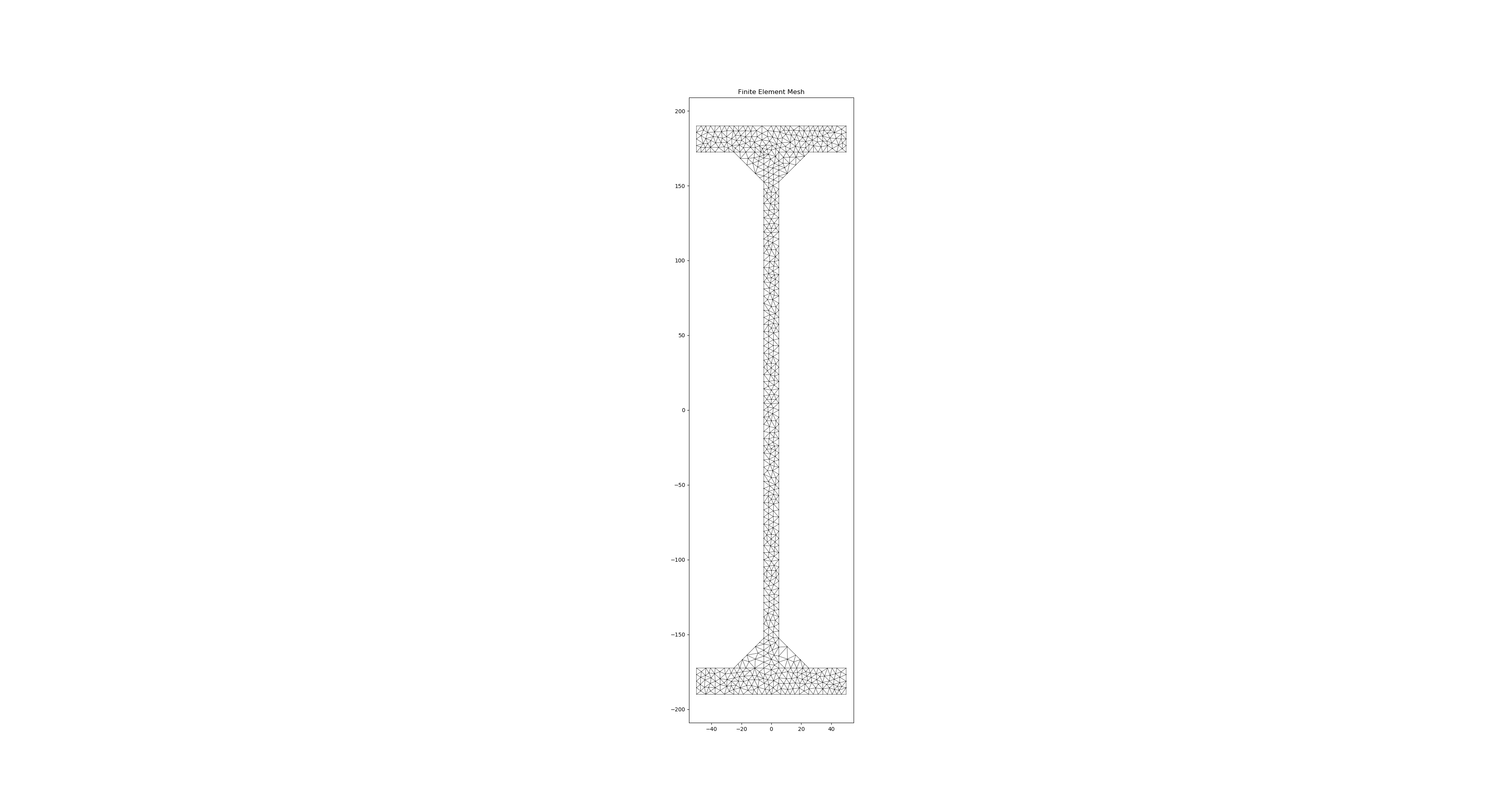
Hi,
my name is Nick and I am a Structural Engineer. I 've been recently using the section-properties package (great work by the way!) to calculate the properties of cross sections that are comprised from at least two unconnected parts (see the picture below), since I could not find any other commercial (e.g. NASTRAN, ABAQUS) that can calculate the properties of such cross sections.

I have two questions:
Is your feature request related to a problem? Please describe.
No
Describe the solution you'd like
Switch at least the plot_centroids method to return the fig,ax objects so they can be properly saved, regardless of execution method.
Describe alternatives you've considered
I've tried implementing a plt.savefig(name) command after calling xsect.plot_centroids(). This will work with pause=False if executed on the command line, however if executed somewhere like a Jupyter notebook, the "current figure" that plt.savefig() grabs is blank (even if pause is True). Some users are getting no plots while I'm getting correct plots. Online users always recommend saving prior to showing, or using the plt.gcf() to return a Figure object for referencing later.
This should be a simple fix by returning fig,ax in the plotting methods. Then, the figure is stored directly in memory and can be addressed by python to fig.savefig() instead.
It may break some existing implementations, if returned objects are not expected. That's why I wanted to bring up an issue rather than jumping straight into a new PR.
Additional context
An object oriented approach with matplotlib is better, in my opinion, than the "default" plt.plot and plt.show. It allows more exact control. Am I missing something obvious?
Hi Robbie.
Have you ever tried to use Numba instead of Numpy?
It seens it can speed up everything :)
Is it worth it to have a look at?
Describe the solution you'd like
Would it be hard for any of the predefined sections to output the external perimeter length (sometimes called profile length in section tables) & surface area/m also? I'm guessing you already have a list of all the nodes making up the overall perimeter outline, and adding up the length of the lines connecting these nodes might be possible?
Why? For design these are used for fire capacity calculations where you need the Hp/A (heated perimeter over area ratio) and in general terms also for paint coverage comparisons between sections comparing surface area to be coated / linear length between varying sections (i.e. might be cheaper to use a thicker/smaller section of the same weight with less paint rather than larger lighter gauge section with more paint due to larger surface area).
Additional context
Many thanks for considering any of these additions!
Is your feature request related to a problem? Please describe.
No
Describe the solution you'd like
Switch at least the plot_centroids method to return the fig,ax objects so they can be properly saved, regardless of execution method.
Describe alternatives you've considered
I've tried implementing a plt.savefig(name) command after calling xsect.plot_centroids(). This will work with pause=False if executed on the command line, however if executed somewhere like a Jupyter notebook, the "current figure" that plt.savefig() grabs is blank (even if pause is True). Some users are getting no plots while I'm getting correct plots. Online users always recommend saving prior to showing, or using the plt.gcf() to return a Figure object for referencing later.
This should be a simple fix by returning fig,ax in the plotting methods. Then, the figure is stored directly in memory and can be addressed by python to fig.savefig() instead.
It may break some existing implementations, if returned objects are not expected. That's why I wanted to bring up an issue rather than jumping straight into a new PR.
Additional context
An object oriented approach with matplotlib is better, in my opinion, than the "default" plt.plot and plt.show. It allows more exact control. Am I missing something obvious?
Method not displayed in docs
Describe the bug
Hi Robbie,
firstly I would like to congratulate you for the great workyou did here with sectionproperties.
I was experimenting with some solvers and I wanted to see the results of your
implementation on some typical cross sections. As a result, I created a small script file
that calculates the centroidal second moments of inertia for a homogeneous rectangular
cross section (d=10., b=10.) but I retrieved results different from those that I've expected.
To Reproduce
This is my script:
import sectionproperties.pre.sections as sections
from sectionproperties.analysis.cross_section import CrossSection
from sectionproperties.pre.pre import Material
def main()
# Material
steel = Material(name='Steel', elastic_modulus=210000, poissons_ratio=0.3,
                 yield_strength=500, color='red')

# Geometry
geometry = sections.RectangularSection(d=10., b=10.)

# Mesh
mesh = geometry.create_mesh(mesh_sizes=[1.])

# Create meshed cross section
section = CrossSection(geometry, mesh, materials=[steel])
section.plot_mesh(materials=True)

# Calculate non-warping dependent properties
section.calculate_geometric_properties()

# Print results
(Ix, Iy, Ixy) = section.get_ic()
print("{0: <5}".format("Ix") + "{0: ^3}".format('=') + "{}".format(Ix))
print("{0: <5}".format("Iy") + "{0: ^3}".format('=') + "{}".format(Iy))
print("{0: <5}".format("Ixy") + "{0: ^3}".format('=') + "{}".format(Ixy))
if name == 'main':
main()
Expected behavior
I would expect that the second moments of inertia would be equal to:
Ix = Iy = 10*(10^3)/12. = 833.333
however the results I get are:
Ix = Iy = 174999999.9999994
Desktop (please complete the following information):
Describe the bug
There is an issue with Geometry.rotate_section where under the default parameters the control point is rotated differently from the section. If rot_point is 'center' then the section is rotated about the center of the bounding box and the control point is rotated about the section's centroid. In general, this results in an unexpected behavior.
This only applies to geometries that have an assigned_control_point.
geometries that do not have an assigned_control_point regenerate a control point after the rotation operation (via shapely representitive_point).
To Reproduce
import sectionproperties.pre.sections as sections
import matplotlib.pyplot as plt

a = 1
b = 2
t = 0.1

points = [[-t/2, -2*a], [t/2, -2*a], [t/2, -t/2], [a, -t/2], [a, t/2],
          [-t/2, t/2]]
facets = [[0, 1], [1, 2], [2, 3], [3, 4], [4, 5], [5, 0]]
holes = []
control_points = [0, 0]

geometry = sections.Geometry.from_points(points, facets, holes, control_points)

fig, (ax1,ax2) = plt.subplots(2)
geometry.plot_geometry(ax = ax1)
geometry = geometry.rotate_section(angle=30)
geometry.plot_geometry(ax=ax2)
plt.show()
Expected behavior
That the control point undergoes the same transformation as the section.
Hi Robbie,
First of all, thanks for the great utility - it's helped us get off the ground on a project with surprisingly little effort.
Is your feature request related to a problem? Please describe.
We are creating meshes of a set of systems with a pretty complex geometry, which means that even with some cleaning of our own we regularly hit the infinite loop reported in #15. Reason being, we have quite a few curves, which naturally introduce shorter facet lengths. Of course we can build from source (and currently are building from source) to work around that but it would be much more convenient if there was a packaged version that included this fix.
Describe the solution you'd like
Create a version 1.0.6 release and package in PyPI.
Describe alternatives you've considered
Build from source and maintenance on our side of installer scripts that allow a user to checkout the repo at 9d74737 and install into their environment.
Additional context
If you're not in a position to release in the short term, it would be helpful to know when you might intend to package your next release - I can see it's been nearly 11 months since the last package.
Hi,
First of all thanks for this library, it's easy to use and fast!
Which formula/reference did you use to determine the shear area? It's not completely clear to me how they are calculated. Furthermore I see a big difference when I calculate the shear area with different methods for a box geometry (60x90, t=5):
Thanks for the feedback!
Describe the bug
I have the situation I was looking at where I have several angles placed to reinforce an I-section. They should all be in contact naturally, but I noted in passing that the shear centre was off an axis of symmetry.

Turns out two of the angles (the ones on the right) are not joined when merging the geometry when you comment out the lines that add the holes within the closed section that is formed you will see the following.

I'm imagining here after creating section, shifting it, and rotating it that some small precision issues are meaning as far as the code is concerned, the sections are not joined by some miniscule amount, so they are therefore not being meshed together. (I have not confirmed this as I'm not quite sure how to look at the raw coordinates of the mesh coordinates or section geometry coordinates).
As far as I can tell there is no merge tolerance exposed the user that might be able to be manipulated to ensure merging occurs as expected?
The overriding issue is you cannot tell the geometry is not joined without being onto it and reviewing and interpreting the results, usually I don't plot the centroids and shear centre for example, only the mesh. Danger is people may not be doing this in all cases and hence getting incorrect results when the expectation is that the inputs given place two geometries in contact, and therefore the expectation is that they are merged.
I've tried constructing the geometry a number of ways and always come up against something not quite connecting. Shifting when creating, then rotating or shifting when creating, then mirroring.
To Reproduce
Try run this, then comment out the addition of the holes. Geometry does not appear to be merged, as without the holes the expectation would be that the mesh would fill the voids created.
import sectionproperties.pre.sections as sections
from sectionproperties.analysis.cross_section import CrossSection

mesh_area = 25  # max mesh size

d = 612  # I section depth
b_f = 229  # I-section flange width
t_f = 19.6  # I-section flange thickness
t_w = 11.9  # I-section web thickness
r_1 = 14  # I-section root radii
n_r = 10  # number of points considered around root radii

d_1 = 100  # strengthening angle leg 1 length
b_1 = 100  # strengthening angle leg 2 length
t = 8  # strengthening angle thickness
r_r = 8  # strengthening root radii
r_t = 5  # strengthening toe radii

# create constituent geometry
# I section
geometry1 = sections.ISection(d=d, b=b_f, t_f=t_f, t_w=t_w, r=r_1, n_r=n_r, shift=[-b_f / 2, -d / 2])

# top right angle
shift = [b_1 + t_w / 2, d / 2 - d_1 - t_f]
geometry2 = sections.AngleSection(d=d_1, b=b_1, t=t, r_r=r_r, r_t=r_t, n_r=n_r, shift=shift)
geometry2.rotate_section(angle=5 * 90, rot_point=shift)

# bottom left angle
shift = [-b_1 - t_w / 2, -d / 2 + d_1 + t_f]
geometry3 = sections.AngleSection(d=d_1, b=b_1, t=t, r_r=r_r, r_t=r_t, n_r=n_r, shift=shift)
geometry3.rotate_section(angle=-90, rot_point=shift)

# top left angle
shift = [-b_1 - t_w / 2, d / 2 - d_1 - t_f]
geometry4 = sections.AngleSection(d=d_1, b=b_1, t=t, r_r=r_r, r_t=r_t, n_r=n_r, shift=shift)

# bottom right angle
shift = [b_1 + t_w / 2, -d / 2 + d_1 + t_f]
geometry5 = sections.AngleSection(d=d_1, b=b_1, t=t, r_r=r_r, r_t=r_t, n_r=n_r, shift=shift)
geometry5.rotate_section(angle=180, rot_point=shift)

# create merged section
geometry = sections.MergedSection([geometry1, geometry2, geometry3, geometry4, geometry5])

# add holes within closed sections formed by adding angles
geometry.add_hole([-b_1 / 2, d / 2 - d_1 / 2])
geometry.add_hole([-b_1 / 2, -d / 2 + d_1 / 2])
geometry.add_hole([b_1 / 2, d / 2 - d_1 / 2])
geometry.add_hole([b_1 / 2, -d / 2 + d_1 / 2])

# create mesh
mesh = geometry.create_mesh(mesh_sizes=[mesh_area, mesh_area, mesh_area, mesh_area, mesh_area])

# clean geometry
geometry.clean_geometry(verbose=True)

# create section
section = CrossSection(geometry, mesh)

# calculate results
section.calculate_geometric_properties()
section.calculate_plastic_properties()
section.calculate_warping_properties()

# plot results
section.plot_mesh()
section.plot_centroids()

# display all results
# check https://sectionproperties.readthedocs.io/en/latest/rst/post.html for definitions
section.display_results(fmt='.3f')
Expected behaviour
Possibly introduce some small tolerance or rounding routine to ensure elements that are within small distances equivalent to some tolerance are in fact merged as per the intent of the user in these situations where the raw inputs place the geometry in contact.
Alternatively (or in addition to) add highlighting on a plot when there are multiple geometries defined that do not share a common perimeter. For example, the perimeter could be highlighted a different colour (like red) on the right angles when no common points are shared between two geometries to highlight non-compliant analysis/inputs to allow user to identify and address?
If the people working on the shapely code could run the same scenario and confirm it works/does not work there it might be helpful to know if the same assumed precision issues are causing the same observation? Sorry have not gotten around to trying it out yet :)
I think it was bought up previously in a discussion regarding having the ability to show the centroids and shear centre in the same plot with the mesh as an option (or alternatively allow optional plotting of the mesh on the centroids plot). This might help identify any immediate issues to a user in an 'all in one' plot scenario when setting up an analysis. I feel this would be a welcome addition to review and debug geometry and results on one plot.
From my perspective completing the code with the added holes there is no feedback that the two right angles are not joined at all. It was only through the shear centre being in a weird location I picked this anomaly up. You can work around it by moving the geometry slightly to ensure an overlap or placing another small geometry to link them, but hopefully a solution could be implemented in the code to either make sure close geometry does merge, or to highlight to the user when it is not merged/joined.
Desktop (please complete the following information):
Is your feature request related to a problem? Please describe.
Request for a monosymmetric I-beam generator function.
Describe the solution you'd like
Generate a monosymmetric I-beam with different top and bottom flange thickness and widths.
Describe alternatives you've considered
N/A
Additional context
N/A
Is your feature request related to a problem? Please describe.
No specific problems, but would increase functionality and simplify a fair bit of the code.
Describe the solution you'd like
Use shapely in all it's glory.
Describe alternatives you've considered
Writing the code yourself - tried that, no fun.
Additional context
Suggesting in issue #9 by Agent6-6-6.
Describe the bug
This highlighted notation is possibly wrong in the documents, based on the form of the other notations, believe it should actually be sigma_zx, Vy?? (in get_stress())

New v2 logo in sectionproperties has three red dots and white space above, see below screenshot:

I'm guessing the white space was added for appropriate github repo logo requirements(?), but looks a bit funny on the home page of the docs? Maybe a different image file could be used for the docs homepage?
I know, really focussing on the big issues...
Describe the bug
Plotting the mesh with materials doesn't show the legend. Also the material colour is not displaying as expected.
To Reproduce
Code example from 'Advanced Geometry'
import sectionproperties.pre.sections as sections
import sectionproperties.analysis.cross_section as cross_section
from sectionproperties.pre.pre import Material

i_sec1 = sections.i_section(d=250, b=150, t_f=13, t_w=10, r=12, n_r=12)
i_sec2 = i_sec1.rotate_section(45)

mat1 = Material("Material_1", 200e3, 0.3, 400, "green")
mat2 = Material("Material_2", 150e3, 0.2, 200, "red")  # Just some differing properties

i_sec1.material = mat1
i_sec2.material = mat2

cut_2_from_1 = (i_sec1 - i_sec2) # locates intersection nodes
sec_1_nodes_added = cut_2_from_1 | i_sec1

analysis_geom = (i_sec2 - i_sec1) + sec_1_nodes_added

analysis_geom.create_mesh([10])
analysis_sec = cross_section.Section(analysis_geom)
analysis_sec.plot_mesh()
Produces plot below:

Expected behaviour
Material one to be green, with a legend displayed.
Additional context
Possibly also related to #94.
Is your feature request related to a problem? Please describe.
Monosymmetry parameter is required for the evaluation of the member capacity of monosymmetric sections and is difficult to compute by hand
Describe the solution you'd like
Calculate the monosymmetry parameter about the x and y axes.
Describe alternatives you've considered
N/A
Additional context
From NZS3404:

More of an FYI in advance of v2.0: when using two materials in a cross section, display_results shows the torsion constant as
G.J = xxx
the reported quantity is (in fact) E * J, which is consistent with the elastic modulus weighting of other composite cross section properties, but the use of "GJ" may be misleading. So the torsion constant should be found like section.get_j()/precast.elastic_modulus if the precast concrete is your reference material.
More broadly, since the Material class is not 'smart' a little hack is to just use E = 1 for your reference material and E = modular_ratio for the secondary material (the Poisson's ratios should still be correct though for shear-related properties).
Describe the solution you'd like
Add a feature to generate properties for tapered flange beams and tapered flange channels. Often these are older sections, which are harder to source printed section properties for, so would seem like a useful addition to the capabilities of your programme.
Older beams often seem to be defined in the following manner:-
root radii
flange radii
flange angle
flange thickness at midpoint

or similarly for channels:-

taken from
Dorman Long 1906 Handbook.pdf
Though I note the US AISC S Shapes and tapered channel shapes are defined slightly differently (and not too clear to me what the intended flange angle and radii are!):-


Describe the bug
First moment of area (Qx, Qy) results seem to be summed over the entire cross-section, which results is a zero-value. Is there a way to get just the Qx, Qy over the top half or bottom half? If you were calculating transverse shear over the section (VQ/Ib), what property do you use to get non-zero results?
To Reproduce
import sectionproperties.pre.nastran_sections as sections
from sectionproperties.analysis.cross_section import CrossSection

shape = sections.ZSection(DIM1=.4, DIM2=0.2, DIM3=.8, DIM4=1.2, shift=[-.2,0])
mesh = shape.create_mesh(mesh_sizes=[0.0005])

xsect = CrossSection(shape, mesh)
xsect.calculate_geometric_properties()
xsect.display_results()
Expected behaviour
Since top and bottom first moments of area should be equal, why not provide one or the other, instead of summing over the whole cross-section?
Desktop (please complete the following information):
Additional context
Possibly not a bug. I may not fully understand how to interpret the results.
I believe you've already solved this in #33 and related updates, however as it hasn't been published on PYPI, just bringing your attention to the fact that Streamilt, which is a library for generating web apps, will soon require any functions that use Matplotlib to return fig.
How it works
Streamlit doesn't display any Matplotlib figures unless you call streamlit.pyplot(fig). If nothing is passed in, Streamlit has previously just run plt.savefig() and outputted which works with SectionProperties module. However, there is a deprecation warning for 1st December 2020 (although they are yet to remove it from the codebase) that advises this will no longer be allowed.
How to replicate
import streamlit as st

# sectionproperties object setup not shown

geometry.plot_geometry()  # plot the geometry

st.pyplot() #Plot the cross section shape of the box girder
Warning given:

Expected behaviour
fig, ax = geometry.plot_geometry()  # plot the geometry

st.pyplot(fig) #Plot the cross section shape of the box girder
At the moment I'm using the following workaround which works, however the figures don't always come our right (e.g. need to manually fix the aspect ratio etc.)
fig,ax = plt.subplots()
geometry.plot_geometry(ax=ax)  # plot the geometry

st.pyplot(fig)
Setup
Streamlit 0.72
section properties 1.07
Hi Robbie
Is your feature request related to a problem? Please describe.
When you are cleaning the geometry of a section with a large number of mesh elements, it can take a significant amount of time (like an hour+ for complex sections) with nothing being fed back to the user to indicate progress if you haven't used verbose=True.
There is currently no feedback on progress through this sometimes lengthy process if verbose=False is used, for example when you display the results for other procedures with (time_info=True) it gives you the time taken and what is being looked at as an analysis is stepped through. The geometry clean routine can take significantly longer than the other section property calculations, but there is no time feedback for this process currently.
Describe the solution you'd like
In its most basic form of timing each geometry clean subroutine it might look like below to provide some ongoing feedback to the user through the clean process in a similar way to all the other time_info code for other calculations. without needing to resort to verbose=True to see if its making progress.
if time_info:
            text = "--Merging close points..."
            solver.function_timer(text, self.zip_points)
            print("")
            text = "--Removing zero length facets..."
            solver.function_timer(text, self.remove_zero_length_facets)
            print("")
            text = "--Removing duplicate facets..."
            solver.function_timer(text, self.remove_duplicate_facets)
            print("")
            text = "--Removing overlapping facets..."
            solver.function_timer(text, self.remove_overlapping_facets)
            print("")
            text = "--Removing unused points..."
            solver.function_timer(text, self.remove_unused_points)
            print("")
            text = "--Rebuilding intersecting facets..."
            solver.function_timer(text, self.intersect_facets)
            print("")
        else:
            self.zip_points()
            self.remove_zero_length_facets()
            self.remove_duplicate_facets()
            self.remove_overlapping_facets()
            self.remove_unused_points()
            self.intersect_facets()
I could spend a small amount of time and follow through altering the required modules if you were in agreement with this as an addition and submit it as a pull request?
Thanks!
A declarative, efficient, and flexible JavaScript library for building user interfaces.
🖖 Vue.js is a progressive, incrementally-adoptable JavaScript framework for building UI on the web.
TypeScript is a superset of JavaScript that compiles to clean JavaScript output.
An Open Source Machine Learning Framework for Everyone
The Web framework for perfectionists with deadlines.
A PHP framework for web artisans
Bring data to life with SVG, Canvas and HTML. 📊📈🎉
JavaScript (JS) is a lightweight interpreted programming language with first-class functions.
Some thing interesting about web. New door for the world.
A server is a program made to process requests and deliver data to clients.
Machine learning is a way of modeling and interpreting data that allows a piece of software to respond intelligently.
Some thing interesting about visualization, use data art
Some thing interesting about game, make everyone happy.
We are working to build community through open source technology. NB: members must have two-factor auth.
Open source projects and samples from Microsoft.
Google ❤️ Open Source for everyone.
Alibaba Open Source for everyone
Data-Driven Documents codes.
China tencent open source team.