Git Product home page Git Product logo

karawin / ka-radio32 Goto Github PK

View Code? Open in Web Editor NEW
510.0 46.0 154.0 204.6 MB

esp32 version of Ka-Radio (https://github.com/karawin/Ka-Radio) by jp Cocatrix

Makefile 0.13% Batchfile 0.01% C 91.48% C++ 5.80% PHP 0.04% Python 0.08% Shell 0.12% HTML 0.02% JavaScript 0.05% CSS 0.01% Uno 0.60% Assembly 1.07% Roff 0.12% R 0.02% M4 0.01% CMake 0.01% SWIG 0.44% D 0.01%
ka-radio32 esp32 webradio vs1053 i2s wroom wrover espressif

ka-radio32's Introduction

STATE

Release 2.3 R0 Stable
ESP-IDF v3.3

See also the version for ESP-IDF v4.4 at
https://github.com/karawin/KaRadio32_4

Works on any esp32 board.
See the boards directory for a list of pre-configured boards.
See : Hardware configuration partition

  • The esp32 adds the output on the internal dac or with i2s to an external dac but only mp3 stations can be played.
    Adding a vs1053 board, all stations can be played.
    On a wrover cpu with external psram, every AAC streams can be played without the vs1053 board.
  • Compatible with esp8266 KaRadio addons.
  • Serial or telnet commands : Interfaces description

Android remote command

A new android application is born:

  • KaRadio Remote Control by Vassilis Serasidis on google Play.

It is an easy and fast WiFi remote control for your KaRadio or KaRadio32 hardware.
With this android app you can select the WebRadio station you want to play, set the volume and get the station information such as Station name, Genre, Bit rate, Meta data and more.
Found it at https://play.google.com/store/apps/details?id=com.serasidis.karadio.rc

Thanks Vassilis.

The facebook group

https://www.facebook.com/groups/162949914181385
Just register and talk to other users.

Added features from KaRadio

Work with i2s, internal DAC or a vs1053.
Output mode set in Setting panel on web page of KaraDio32 :

  • I2S for connection to an external DAC
  • I2SMERUS to connect a merus amplifier
  • DAC to use the built in DAC of the esp32
  • PDM to output a PDM (Pulse Density Modulation) stream
  • VS1053 to connect to a vs1053 board, I2S output of the vs1053 enabled.
  • all VS1053 tones control
  • AAC decoding on I2S with a wrover cpu (4mB of external psram). Mp3 only on I2S with a wroom cpu.
  • https stations are played.

Others features :

  • Interfaces available on serial, telnet and html
  • up to 255 editable stations.
  • Handles bitrates up to 320 kbps.
  • Stations can be saved and restored from html in and from a file.
  • Hardware configuration file to adapt the standard delivery to all boards and addons you need.
  • all configurable parameters automatically saved.
  • mDNS support.
  • wrover esp32 support. About 10 seconds of buffering, and soon A2DP support (sink and source)
  • Time Zone Offset support.
  • Latin, Cyrillic and Greek support on screen.
  • 28 types of lcd or oled B/W or Color supported.
  • Programmable lcd backlight off timer.
  • Touch screen if the hardware supports it.
  • Two joysticks (set of two adc buttons), one for volume, one for stations.
  • Two max rotary encoders. One for volume priority, one for station change priority.
  • Two max set of 3 buttons. One for volume priority, one for station change priority.
  • Rotary encoder and set of buttons support included. Common functions : play/stop, volume, station change, date time display.
  • ADC keyboard with 6 buttons.
  • Date format DD:MM:YYYY or MM:DD:YYYY .
  • Remote IR support integrated. Nec protocol only.
  • Two configurable access points .
  • OTA (Over The Air) update of the software.
  • many more configurable parameters. See Interfaces document

Played stream

CPU vs1053b other
Wroom mp3 aac ogg mp3
Wrover mp3 aac ogg mp3 aac

Buffering audio

CPU vs1053b other
Wroom http 60k 45k
Wroom https 50k 25k
Wrover http 400k 400k
Wrover https 400k 400k

Configure the hardware and IR codes

If the default configuration doesn't fit your needs, you can externally configure the software to fit your hardware and peripherals to suit your needs.
The configuration file is to be flashed only one time. After, the standard delivery will become compatible with your hardware gpio use and peripherals configuration. A future standard OTA will automatically works for your configuration.
See : Hardware configuration partition
For a wrover cpu you need a csv file with psram in the name. Without it, the default configuration will fail.

Build your own

=======
To build your own release if you want to do some improvments, you must install the idf https://github.com/espressif/esp-idf and the toolchain. The esp-idf release is the 3.3.5

ESP-IDF Patch

Since the 3.3.5 and upper releases there is a bug with CONFIG_SPIRAM_IGNORE_NOTFOUND You need to patch the esp\esp-idf\components\esp32\spiram.c line 128 to

esp_spiram_size_t esp_spiram_get_chip_size()
{
    if (!spiram_inited) {
#if CONFIG_SPIRAM_IGNORE_NOTFOUND
         ESP_EARLY_LOGE(TAG, "SPI RAM not initialized");
		 return ESP_SPIRAM_SIZE_INVALID;
#endif		
		 abort();
    }

See espressif/esp-idf#6063 (comment)

To flash all build output, run 'make flash' or :

python /home/yourhome/esp/esp-idf/components/esptool_py/esptool/esptool.py \
   --chip esp32 --port com5 --baud 460800 --before default_reset \
   --after hard_reset write_flash -u --flash_mode dio \
   --flash_freq 40m --flash_size detect \
   0x1000 /home/yourhome/esp/Ka-Radio32/build/bootloader/bootloader.bin \
   0x10000 /home/yourhome/esp/Ka-Radio32/build/KaRadio32.bin \
   0x8000 /home/yourhome/esp/Ka-Radio32/build/partitions.bin

GPIO Definition

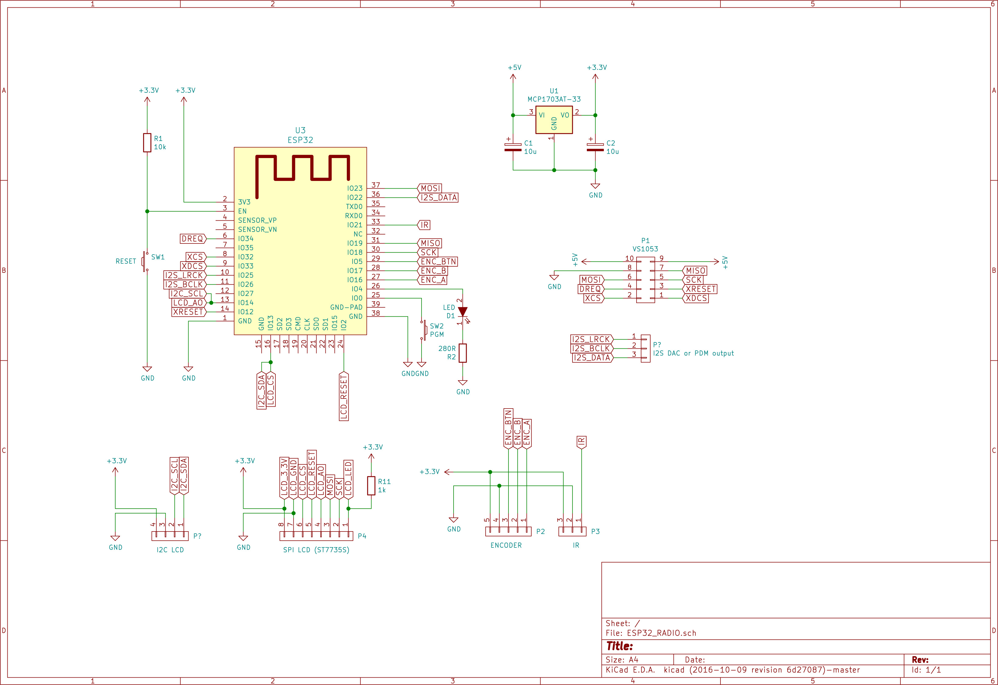
The default configuration is given below. It includes an encoder, an IR remote and a LCD or OLED.
To add or edit GPIO definitions and add or remove some devices, you may need a hardware configuration file. Some examples are in the boards directory.
See the file main/include/gpio.h and main/include/addon.h
WARNING: this configuration will not work for a wrover processor. You need an adapted csv configuration.

//--------------------------------------//
// Define GPIO used in KaRadio32        //
// if no external configuration is used //
//--------------------------------------//
// Compatible ESP32 ADB
// https://www.tindie.com/products/microwavemont/esp32-audio-developing-board-esp32-adb/
// Default value, can be superseeded by the hardware partition.

// Must be HSPI or VSPI

#define KSPI VSPI_HOST

// KSPI pins of the SPI bus
//-------------------------
#define PIN_NUM_MISO GPIO_NUM_19 	// Master Input, Slave Output
#define PIN_NUM_MOSI GPIO_NUM_23	// Master Output, Slave Input   Named Data or SDA or D1 for oled
#define PIN_NUM_CLK  GPIO_NUM_18 	// Master clock  Named SCL or SCK or D0 for oled

// status led if any.
//------------------- 
// Set the right one with command sys.led
// GPIO can be changed with command sys.ledgpio("x")
#define GPIO_LED	GPIO_NUM_4		// Flashing led or Playing led

// gpio of the vs1053
//-------------------
#define PIN_NUM_XCS  GPIO_NUM_32
#define PIN_NUM_RST  GPIO_NUM_12 
#define PIN_NUM_XDCS GPIO_NUM_33
#define PIN_NUM_DREQ GPIO_NUM_34
// + KSPI pins

// Encoder knob
//-------------
#define PIN_ENC0_A   GPIO_NUM_16	//16	// 255 if encoder not used
#define PIN_ENC0_B   GPIO_NUM_17	//17	// DT
#define PIN_ENC0_BTN GPIO_NUM_5		//5// SW
#define PIN_ENC1_A   GPIO_NONE		// 255 if encoder not used
#define PIN_ENC1_B   GPIO_NONE		// DT
#define PIN_ENC1_BTN GPIO_NONE		// SW

// 3 Buttons
//-------------
#define PIN_BTN0_A   GPIO_NONE		
#define PIN_BTN0_B   GPIO_NONE		
#define PIN_BTN0_C   GPIO_NONE		
#define PIN_BTN1_A   GPIO_NONE		
#define PIN_BTN1_B   GPIO_NONE		
#define PIN_BTN1_C 	 GPIO_NONE		

// Joystick (2 buttons emulation on ADC)
//--------------------------------------
#define PIN_JOY_0	GPIO_NONE
#define PIN_JOY_1	GPIO_NONE

// I2C lcd (and rda5807 if lcd is i2c or LCD_NONE)
//------------------------------------------------
#define PIN_I2C_SCL GPIO_NUM_14
#define PIN_I2C_SDA GPIO_NUM_13
#define PIN_I2C_RST	GPIO_NUM_2		// or not used


// SPI lcd
//---------
#define PIN_LCD_CS	GPIO_NUM_13		//CS
#define PIN_LCD_A0	GPIO_NUM_14		//A0 or D/C
#define PIN_LCD_RST	GPIO_NUM_2		//Reset RES RST or not used
// KSPI pins +

// IR Signal
//-----------
#define PIN_IR_SIGNAL GPIO_NUM_21	// Remote IR source


// I2S DAC or PDM output
//-----------------------
#define PIN_I2S_LRCK GPIO_NUM_25	// or Channel1
#define PIN_I2S_BCLK GPIO_NUM_26	// or channel2
#define PIN_I2S_DATA GPIO_NUM_22	//  

// ADC for keyboard buttons
#define PIN_ADC	GPIO_NONE	//GPIO_NUM_32 TO GPIO_NUM_39 or GPIO_NONE if not used.

// LCD backlight control
#define PIN_LCD_BACKLIGHT	GPIO_NONE // the gpio to be used in custom.c 

// touch screen  T_DO is MISO, T_DIN is MOSI, T_CLK is CLk of the spi bus
#define PIN_TOUCH_CS	GPIO_NONE //Chip select T_CS

LCD or oled declaration

You can configure the kind of display used in your configuration with the command
'sys.lcd("x")' with x:

#define LCD_NONE		255

// Black&White
//I2C
#define LCD_I2C_SH1106		0 //128X64
#define LCD_I2C_SSD1306		1 //128X64
#define LCD_I2C_SSD1309		2 //128X64
#define LCD_I2C_SSD1325 	3 //128X64
#define LCD_I2C_SSD1306NN	4 //128X64
#define LCD_I2C_SSD1309NN	5 //128X64
#define LCD_I2C_SSD1306UN	6 //128x32
#define LCD_I2C_ST7567		7 //64x32

//SPI
#define LCD_SPI_SSD1306 		64 //128X32 (LCD_SPI =0x40)
#define LCD_SPI_SSD1309 		65 //128X64
#define LCD_SPI_ST7565_ZOLEN	66 //128X64
#define LCD_SPI_SSD1322_NHD		67 //256X64
#define LCD_SPI_IL3820_V2		68 //296X128
#define LCD_SPI_SSD1607			69 //200X200
#define LCD_SPI_LS013B7DH03		70 //128X128
#define LCD_SPI_SSD1306NN 		71 //128X64
#define LCD_SPI_SSD1309NN 		72 //128X64
#define LCD_SPI_ST7920 			73 //128X64
#define LCD_SPI_ST7567_pi 		74 //132X64
#define LCD_SPI_ST7567	 		75 //64X32
#define LCD_SPI_ST7565_NHD_C12864	76 //128X64

// Colors
#define LCD_SPI_ST7735			192 // 128x160  (LCD_COLOR|LCD_SPI =0xC0)
#define LCD_SPI_SSD1351			193 // 128x128
#define LCD_SPI_ILI9341			194 // 240x320
#define LCD_SPI_ILI9163			195 // 128x128
#define LCD_SPI_PCF8833			196 // 132x132
#define LCD_SPI_SSD1331			197 // 96x64
#define LCD_SPI_SEPS225			198 // 96x64
#define LCD_SPI_ST7789V			199 // 240x320
#define LCD_SPI_ST7735S			200 // 128x128
#define LCD_SPI_ST7735L			201 // 80x160
#define LCD_SPI_ST7735W			202 // 128x160 shifted 2+1
#define LCD_SPI_ST7789S			203 // 240x240
#define LCD_SPI_ST7789T			204 // 135x240

First use

  • If the access point of your router is not known, the webradio initialize itself as an AP. Connect the wifi of your computer to the ssid "WifiKaRadio",
  • Browse to 192.168.4.1 to display the page, got to "setting" "Wifi" and configure your ssid ap, the password if any, the wanted IP or use dhcp if you know how to retrieve the dhcp given ip (terminal or scan of the network).
  • In the gateway field, enter the ip address of your router.
  • Validate. The equipment restart to the new configuration. Connect your wifi to your AP and browse to the ip given in configuration.
  • Congratulation, you can edit your own station list. Don't forget to save your stations list in case of problem or for new equipments.
  • if the AP is already know by the esp32, the default ip is given by dhcp.
  • a sample of stations list is on http://karadio.karawin.fr/WebStations.txt . Can be uploaded via the web page.

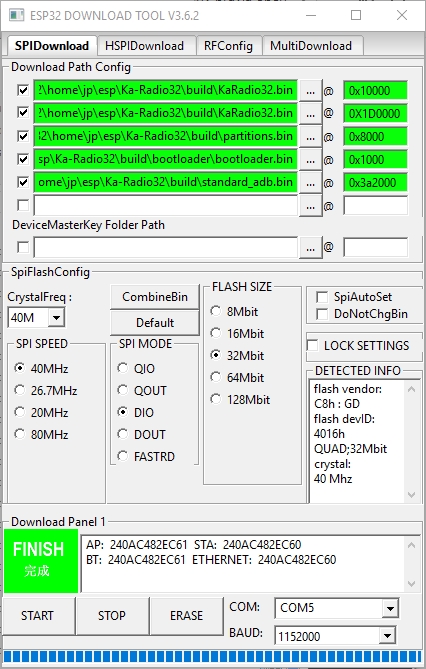
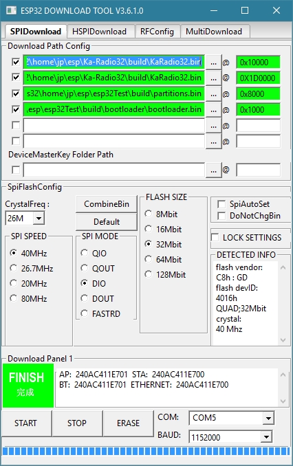
To flash your KaRadio32 without generating it, you will need the files in the binaries directory.

The tool to use is here :
http://espressif.com/en/support/download/other-tools
(change the security of the installation directory to permit all)

See the image at :
http://karadio.karawin.fr/karawin32Flash.jpg
WARNING: the standard_adb.bin must be changed for a wrover processor or another configuration.

Screenshoot of download tool

The scheme from tomasf71 :

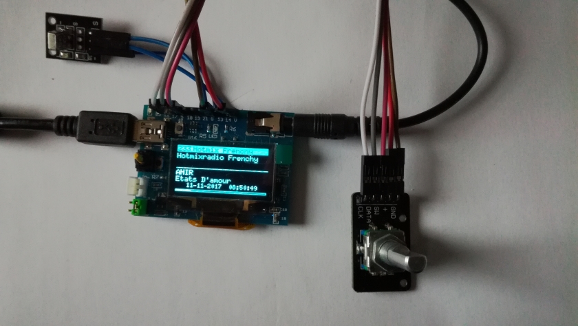
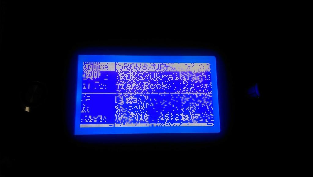
Just an example of a realization.

Scheme

Audio output

In the Setting panel on the webpage of KaraDio32 you can set the desired output method for audio.

For output on a simple speaker or a general analog amplifier :

For output via addional I2S or VS1053 hardware :

  • I2S for connection to ac external DAC
  • I2SMERUS to connect a merus amplifier
  • VS1053 to connect to a vs1053 board.

Connecting a speaker, earphone or amplifier with DAC or PDM setting

You can connect the GPIO25 (left audio channel), GPIO26 (right audio channel) and Ground directly to a small loudspeaker, a simple earphone (like from an mp3 player) or the input of an analog amplifier. The quality is less perfect than using an I2S or VS1053 board, bit it is very simple hardware-wise.

Connect like this :

                         +------------------------------------+
ESP32-GPIO25 (left) -----+speaker/earphone/analog-amp (left)   +-----+
                         +------------------------------------+      |
                                                                     |
                         +------------------------------------+      |
ESP32-GPIO26 (right) ----+speaker/earphone/analog-amp (right  +------+
                         +------------------------------------+      |
                                                                     |
ESP32-GROUND --------------------------------------------------------+

Reducing the analog output level

If the audio signal level is too high for your speaker, earphone or amplifier you can add a potentiometer to decrease the level. Connect the potentiometer like this (only pictured for 1 audio channel, for stereo you need 2 potentiometers or a stereo-potmeter.

                                     +--------------------------------------+
ESP32-GPIO25 (left) -------+   +-----+speaker/earphone/analog-amp (left)    +------+
                          +-+  |     +--------------------------------------+      |
                          +P+  |                                                   |
                          +o+--+                                                   |
                          +t+                                                      |
                          +++                                                      |
                           |                                                       |
ESP32-GROUND --------------+-------------------------------------------------------+

Improving the audio quality with a filter

An analog DAC signal always has some noise that may cause some distortion on the audio output, especially on low volume passages in the sound. This noise can be decreased with a low-pass filter. The digital PDM signal needs allways low pass filter to convert the digital signal to an analog signal. Fortunately the speaker and earphone acts as a low pass filter, although not in a perfect way.

You can improve the analog signal with an external low-pass filter. A simple low-pass RC filter can be find on the internet, f.i. here :
http://www.pavouk.org/hw/usbdac/en_index.html.

Radio streams

If Karadio32 is configured to use ADC, PDM or I2S output (to an external dac) it can play audio streams in mp3 format. Other formats like AAC and WMV require too much dynamic memories and can not be played this way.

When you want to play other formats you add an external VS1053 decoder to Karadio. Details on the features of this decoder can be found here : http://www.vlsi.fi/en/products/vs1053.html

Many boards can be found at :
https://www.aliexpress.com/wholesale?catId=0&initiative_id=SB_20180113141636&SearchText=vs1053b

Handling streaming errors

Normally a radio station is played without interruption.

But when a connection to the server of the radio station is (temporarily) disrupted (due to internet problems or server problems) Karadio behaves as follows:

  • Playing of the radio stream stops, after a short while Karadio retries to relaunch the connection to the radio stream.
  • If the relaunch of the connection fails again, the webpage of Karadio then shows “invalid address” and goes into the stop state. If you have a display connected to Karadio it will then show the Date, Time and IP address.
  • You can try to relaunch the connection manually by pressing “play” on the Karadio webpage, or resetting the ESP32.
  • If the wifi is disconnected, the esp is rebooted.

List of sources and components adapted for KaRadio32

Encoder an Oled display

ka-radio32's People

Contributors

acruzde avatar h1aji avatar joaofl avatar karawin avatar pepelnyy avatar tonymac32 avatar

Stargazers

 avatar  avatar  avatar  avatar  avatar  avatar  avatar  avatar  avatar  avatar  avatar  avatar  avatar  avatar  avatar  avatar  avatar  avatar  avatar  avatar  avatar  avatar  avatar  avatar  avatar  avatar  avatar  avatar  avatar  avatar  avatar  avatar  avatar  avatar  avatar  avatar  avatar  avatar  avatar  avatar  avatar  avatar  avatar  avatar  avatar  avatar  avatar  avatar  avatar  avatar  avatar  avatar  avatar  avatar  avatar  avatar  avatar  avatar  avatar  avatar  avatar  avatar  avatar  avatar  avatar  avatar  avatar  avatar  avatar  avatar  avatar  avatar  avatar  avatar  avatar  avatar  avatar  avatar  avatar  avatar  avatar  avatar  avatar  avatar  avatar  avatar  avatar  avatar  avatar  avatar  avatar  avatar  avatar  avatar  avatar  avatar  avatar  avatar  avatar  avatar

Watchers

 avatar  avatar  avatar  avatar  avatar  avatar  avatar  avatar  avatar  avatar  avatar  avatar  avatar  avatar  avatar  avatar  avatar  avatar  avatar  avatar  avatar  avatar  avatar  avatar  avatar  avatar  avatar  avatar  avatar  avatar  avatar  avatar  avatar  avatar  avatar  avatar  avatar  avatar  avatar  avatar  avatar  avatar  avatar  avatar  avatar  avatar

ka-radio32's Issues

Feature Request: Hardware Button Control

Hi,

it would be great to select the stations with dedicated Buttons. For example in combination with a MPR121 breakout-board which has a I2C Interface and 12 possible inputs, even with capacitive sensing.
The rotary encoder is great to control the volume, but to switch between the first stations in the list it would be much easier with simple buttons - like on the good old car radios.

ESP32-COLOR-ADB hangs when SSD1331 was enabled

Hello.
I have a trouble with ESP32-COLOR-ADB from Microwavemont (tindie.com).
This board have PCM5102 DAC and SSD1331 OLED on board.

I checked out this project and flashed it this board with default configuration.
Opened web interface and setup wifi connection and loaded my playlist.
After reboot I was able to connect to web interface and play radio.
OLED was disabled at all.

Than I tried to enable OLED by changing SPI pins for OLED

in main/include/gpio.h this way

@@ -48,9 +48,9 @@
// SPI lcd
//---------
// HSPI pins +
-#define PIN_LCD_CS GPIO_NUM_13 //CS
-#define PIN_LCD_A0 GPIO_NUM_14 //A0 or D/C
-#define PIN_LCD_RST GPIO_NUM_2 //Reset RES RST or not used
+#define PIN_LCD_CS GPIO_NUM_5 //CS
+#define PIN_LCD_A0 GPIO_NUM_16 //A0 or D/C
+#define PIN_LCD_RST GPIO_NUM_17 //Reset RES RST or not used

and flash updated code to the board

Than I set current LCD type via telnet

sys.lcd("197");

and reboot

OLED shows some info and blinking once in 2 seconds.

Board can't connect to the wifi and doesn't respond to web requests, telnet and even ping to its IP.

Could you help with issue?
Should I change something else to enable OLED on this board?
Is my OLED pins configuration OK?

Board pin assignment is here
https://cdn.tindiemedia.com/images/resize/qOo86qvwCBgHBnt77bsAibHUS6k=/p/fit-in/1300x866/filters:fill(fff)/i/73055/products/2018-02-08T01%3A02%3A33.164Z-ESP32-ad2.png

Another question, can I change default LCD type to 197 instead of default 0?
Where is right place in code to set this type?

Greater apps?!

I suggested new functions for this project :)
1 add driving gpio (15?) function power on-off over IR
2 add rssi signal on LCD :)
3 add local update over LAN
I did it but my code is not very optimal for displaying the signal. Please support me.
Best regards

wifi.discon not work

Command wifi.discon only reconnect connection and print message WIFI.DISCONNECT FAILED

Launch failed

Hello JP. Have a nice day!
I already several times face the following problem. At the first start, I get an error of the RDA module.

E (6729) i2c: Z:/esp/esp-idf/components/driver/i2c.c:1008 (i2c_master_read):i2c data read length error ESP_ERROR_CHECK failed: esp_err_t 0x102 at 0x401360ff
file: "Z:/msys32/home/Alex/Karadio_orig_096/components/RDA5807/common.c" line 67
func: i2c_slave_read_only
expression: i2c_master_read(cmd, buf,len-1, ACK_VAL)

Backtrace: 0x4008b256:0x3ffcbd20 0x4008b61d:0x3ffcbd40 0x401360ff:0x3ffcbd60 0x40136216:0x3ffcbd80 0x4013633a:0x3ffcbda0 0x401359ad:0x3ffcbdc0 0x4010f7cf:0x3ffcbdf0 0x400d0e26:0x3ffcbe40

Entering gdb stub now.
$T0b#e6

The firmware is standard, taken from here. The electrical circuit is also taken here.
It seems to me that this is due to the choice of display. I chose type 0 (do not use). This causes a device conflict on the I2C bus when testing a non-existent RDA module
Tnx. Alex.

Strong feedback

Hello J.P. I want to use the radio as an alarm clock. And to ensure reliability (I don't want to oversleep!) I need strong feedback, which shows that the stream is really played. Is there something suitable?
Thanks.
P.S. This can also be used for autorestart a "hung" station.

New feature suggestion : Touch control of Ka Radio 32

This is a suggestion for an additional feature to use the ESP32 "touch" feature in Ka Radio 32.

Now that I have attached an Oled display to my KaRadio-32 I think it would be great to control Karadio without using the webpage.

The use of the “ESP32 touch” feature to control Karadio32 would be a nice addition, ref:
http://esp-idf.readthedocs.io/en/latest/api-reference/peripherals/touch_pad.html

I have seen an addon with mechanical microswitches for controls (the ESP8266 version?) so maybe the basic code is in place and adding touch control is not too complicated.

Looking at my Oled SSD1306 display the use of the metallic islands of the mounting holes would make excellent touch-controls. As far as I can see the islands are not connected to the rest of the PCB. It would require:

  • 4 additional wires from the mounting holes to the ESP32 touch GPIO's
  • and ofcourse software changes

karadio ssd1306 touch

**ERROR** multiple definition of `ucg_font_crox3c'

/home/hmurad/esp/Ka-Radio32/build/ucglib/libucglib.a(ucg_karadio32_fonts.o):(.rodata.ucg_font_crox3c+0x0): multiple definition of `ucg_font_crox3c'
/home/hmurad/esp/Ka-Radio32/build/ucglib/libucglib.a(ucg_font_crox3c.o):(.rodata.ucg_font_crox3c+0x0): first defined here
collect2: error: ld returned 1 exit status
make: *** [/home/hmurad/esp/esp-idf/make/project.mk:411: /home/hmurad/esp/Ka-Radio32/build/KaRadio32.elf] Error 


I am trying to compile and seeing this error.
Is it possible to fix?

KaraDio32 with PCM5102 I2S DAC

I use ESP32 with PCM5102 I2S DAC.
The project perfectly works with your bin files, too works with the OTA updates.

I want to add the IR codes.

But when I compile the project itself, there are problems with a sound, fast playback with noise and clicks. I have tried esp-idf versions from the last to esp-idf-v2.1. but I don't receive a correct sound.

WebServer fails on ESP32-Pico-D4

Hello! I have made my KaRadio32 using ESP32-Pico-D4 board taken from here => https://www.aliexpress.com/item/TTGO-Micro-32-Wifi-wireless-Bluetooth-Module-ESP32-PICO-D4-IPEX/32870840371.html
I have built own firmware (to change some GPIOs), but there's one issue - KaRadio's internal webserver crashes after a couple of webpage updates, seems to be it is out of memory, but music is still playing.
UART output:
ets Jun 8 2016 00:22:57

rst:0xc (SW_CPU_RESET),boot:0x13 (SPI_FAST_FLASH_BOOT)
configsip: 188777542, SPIWP:0xee
clk_drv:0x00,q_drv:0x00,d_drv:0x00,cs0_drv:0x00,hd_drv:0x00,wp_drv:0x00
mode:DIO, clock div:2
load:0x3fff0018,len:4
load:0x3fff001c,len:2980
load:0x40078000,len:0
load:0x40078000,len:11400
entry 0x40078c38
I (91) main: starting app_main()
I (91) main: RAM left: 136052
E (91) main: Running partition type 0 subtype 16 (offset 0x00010000)
I (131) main: Partition init done...
Log level is now ESP_LOG_ERROR
E (1741) vs1053: NO VS1053 detected
E (1741) main: LCD Type 0
X: 128, YY: 64, Y: 9
WIFI TRYING TO CONNECT TO SSID 1
E (3181) wifi: esp_wifi_disconnect 954 wifi not start
E (4431) event: invalid static ip
E (4431) main:
Wifi connected

DNS: 192.168.99.1
IP: 192.168.99.230

Init ............... Done
READY. Type help for a list of commands
autostart: playing:1, currentstation:249
##CLI.NAMESET#: 249 Супердискотека 90х
##CLI.URLSET#: online.radiorecord.ru
##CLI.PATHSET#: /sd90_128
##CLI.PORTSET#: 8102
##CLI.OVOLSET#: 0
##CLI.VOL#: 203
##CLI.ICY0#: \/sd90_128
##CLI.ICY3#: http:\/\/savonet.sf.net
##CLI.ICY4#: Misc
##CLI.ICY5#: 128
##CLI.ICY6#: Liquidsoap Radio!
##CLI.ICY7#:  channels=2;samplerate=44100;bitrate=128
##CLI.PLAYING#
##CLI.META#: YAKI-DA - I Saw You Dancing
E (16121) servers: Server low mem. Retrying...
E (18111) rmt: RMT[0] ERR
E (18111) rmt: status: 0x14000040
E (18801) servers: Server low mem. Retrying...
E (28691) servers: Server low mem. Retrying...
E (29091) servers: WebServer Socket fails accept errno: 23
E (30731) servers: WebServer Socket fails accept errno: 23
E (31101) servers: WebServer Socket fails accept errno: 23
E (31211) servers: WebServer Socket fails accept errno: 23
E (31321) servers: WebServer Socket fails accept errno: 23

sys.heap
##SYS.HEAP: 23156 #

After this, webserver is unavailable.

SSD1306 display shifted 1 pixel to the right?

Hi,

I attached an SSD1306 Oled today on my Ka-Radio32 ESP32. It's an I2C display without an RST line.

karadio lcd

The display works (almost) perfectly, but it looks like the pixels that should be in the last column on the right are displayed in the first column on the left (see arrows in my JPG).

It seems like the entire screen is scrolled to the right by 1 pixel, and the last pixel of the line is displayed in the 1st column of the Oled.

I have tried the following, but it makes no difference

  • resetting the ESP32
  • removed power from the ESP32/Oled
  • replaced the Oled by another Oled

Karadio version is V0.9 R2.

Thanks for an excellent piece of software!

fatal error: crypto\sha1_i.h: No such file or directory

Any idea to resolve the following issue when running this command.

make -j5 clean; make -j5; make flash

issue:
...
..
.
CC build/libsodium/libsodium/src/libsodium/sodium/version.o
CC build/libsodium/port/crypto_hash_mbedtls/crypto_hash_sha256_mbedtls.o
CC build/libsodium/port/crypto_hash_mbedtls/crypto_hash_sha512_mbedtls.o
AR build/libsodium/liblibsodium.a
CC build/main/ClickEncoder.o
In file included from /Users/ossama/esp/Ka-Radio32/main/include/webserver.h:13:0,
from /Users/ossama/esp/Ka-Radio32/main/./ClickEncoder.c:20:
/Users/ossama/esp/Ka-Radio32/main/include/websocket.h:18:27: fatal error: crypto\sha1_i.h: No such file or directory
compilation terminated.
make[1]: *** [ClickEncoder.o] Error 1
make: *** [component-main-build] Error 2

Wake function not working properly

I am going to build a web radio based alarm clock with ESP-32, and I am very happy with your implementation. However I have found that the Wake function doesn't work as expected. It was 9:30, I paused the radio, set the wake time to 10:00, but the radio started playing in about 3 minutes. Am I doing anything wrong, or is there a bug?

When I find some time, I will also try to implement a week-day dependent waking times. In the mean time, thanks for this great project!

Permanently reboot

A wonderful project!
Thank you very much for your work!
I have a couple of questions and suggestions.

If I specified an incorrect login and password from WiFi, the controller starts an "permanently reboot"

    if (getAutoWifi()) 
	{
		ESP_LOGE(TAG, "\nWifi Disconnected. reboot");

// esp_restart(); // I comment this line
ESP_LOGE(TAG, "\nWifi Disconnected. Connection tried again"); // uncomment
esp_wifi_connect(); // uncomment
} else
ESP_LOGE(TAG, "\nWifi Disconnected.");
break;

Can return everything back?
Can make control the music playback from the line input/SD card? My VS1053 has it on board.
Сan make a "truncated" version - without a built-in MP3 encoder (only for output on VS1053), but with a large buffer under Stream?
Thank you!

The following tasks did not reset the watchdog in time

Hi @karawin,

This message is generate sometimes while it is running, other times when changing the radio station. Webradio stops and sound settings is lost and elevate to up range:

E (305395) webclient: Client socket: 56 read: -1 errno:11
##CLI.STOPPED# from try restart
Task watchdog got triggered. The following tasks did not reset the watchdog in time:

  • IDLE (CPU 0)
    Tasks currently running:
    CPU 0: clientTask
    CPU 1: timerTask

i use esp32 live mini kit

It is possible to include network speed information used under karadio version and dbm info?

thanks

Ka-Radio32 crash while changing presets via UART

I made a small board with Arduino and IR receiver and couple of buttons for favorite preset selection.
After sending a few commands to the Radio like Serial.print("cli.play("5")\r"); or Serial.print("cli.next\r"); the Radio crashes with following error.
It crashes also when sending the commands via serial console from PC.

ERROR A stack overflow in task uartInterfaceTa has been detected.
abort() was called at PC 0x4008b3c0 on core 1

Backtrace: 0x4008b2de:0x3ffdc0e0 0x4008b3a7:0x3ffdc100 0x4008b3c0:0x3ffdc120 0x400877b8:0x3ffdc140 0x4008966c:0x3ffdc160 0x40089622:0x3ffdc9f0

Entering gdb stub now.
$T0b#e6+$#00

Feature request : Restart Wifi connection after connection is lost

Hi,

Would it be possible to restart the Karadio32 Wifi connection to the Wifi router when the connection was lost?

Background:
Karadadio is very stable for me. It often plays a station for < 24 hours without any issue.

But sometimes Karadio32 looses the Wifi connection. On the LCD a.o. the time is displayed in a BIG font, instead of the Radio details. If you try to connect to the webpage it does not connect. So my conclusion is that the software is still running but that the Wifi connection was lost for some reason.

My Wifi signal is not perfect, so that may be the reason why Kardaio32 was disconnected from the Wifi router.

Would be great if Karadio would restart the Wifi connection is the connection was lost for some reason.

Thx for an excellent piece of software!

M5Stack ILI9341 rather not work

I configured addon.h and gpio.h as following:

#define LCD_COLOR 128 //0x80
#define LCD_SPI 194 //0x40
#define LCD_I2C 0
#define LCD_NONE 255

#define PIN_LCD_CS GPIO_NUM_14 //CS
#define PIN_LCD_A0 GPIO_NUM_27 //A0 or D/C
#define PIN_LCD_RST GPIO_NUM_33 //Reset RES RST or not used`

compiled OK, stations receive OK
sys.lcd
##LCD is 194#

but after start I see very very slowly LCD filling with light blue and nothing more.

UPD:
With WROVER-KIT tested ILI9341 and SSD1351. In both cases the same bug, see attachment.
display_bug

how to use in platformio atom ?

please can anyone explain me how can i use this project in platfromio atom editor?
i clone the project in atom but i can't build it.
thank you.

Suggestion : Add Audio Output section to README

Hi,

While experimenting I created some extra description for "Audio output", maybe you can use it for the README.

Thx.


Audio output

In the Setting panel on the webpage of KaraDio32 you can set the desired output method for audio.

For output on a simple speaker or a general analog amplifier

For output via addional I2S or VS1053 hardware

  • I2S for connection to ac external DAC
  • I2SMERUS to connect a merus amplifier
  • VS1053 to connect to a vs1053 board.

Connecting a speaker, earphone or amplifier with DAC or PDM setting

You can connect the GPIO25 (left audio channel), GPIO26 (right audio channel) and Ground directly to a small loudspeaker, a simple earphone (like from an mp3 player) or the input of an analog amplifier. The quality is less perfect than using an I2S or VS1053 board, bit it is very simple hardware-wise.

Connect like this

                         +------------------------------------+
ESP32-GPIO25 (left) -----+speaker/earphone/analog-amp (left)   +-----+
                         +------------------------------------+      |
                                                                     |
                         +------------------------------------+      |
ESP32-GPIO26 (right) ----+speaker/earphone/analog-amp (right  +------+
                         +------------------------------------+      |
                                                                     |
ESP32-GROUND --------------------------------------------------------+

Reducing the analog output level

If the audio signal level is too high for your speaker, earphone or amplifier you can add a potentiometer to decrease the level. Connect the potentiometer like this (only pictured for 1 audio channel, for stereo you need 2 potentiometers or a stereo-potmeter.

                                     +--------------------------------------+
ESP32-GPIO25 (left) -------+   +-----+speaker/earphone/analog-amp (left)    +------+
                          +-+  |     +--------------------------------------+      |
                          +P+  |                                                   |
                          +o+--+                                                   |
                          +t+                                                      |
                          +++                                                      |
                           |                                                       |
ESP32-GROUND --------------+-------------------------------------------------------+

Improving the audio quality with a filter

An analog DAC signal always has some noise that may cause some distortion on the audio output, especially on low volume passages in the sound. This noise can be decreased with a low-pass filter. The digital PDM signal needs allways low pass filter to convert the digital signal to an analog signal. Fortunately the speaker and earphone acts as a low pass filter, although not in a perfect way.

You can improve the analog signal with an external low-pass filter. A simple low-pass RC filter can be find on the internet, f.i. here : http://www.pavouk.org/hw/usbdac/en_index.html.

Solved : Ka-Radio32 firmware upload problem using ESPTOOL on Mac

Hi,

I would like to try Ka-Radio 32 on my DOIT ESP32 DEVKIT V1 board, but hit a problem.

I downloaded:
http://karadio.karawin.fr/KaRadio32.bin
and
http://karadio.karawin.fr/KaRadio32sup.zip

Since I'm on a Mac I cannot use the Windows flasher so I used ESPTOOL:

imac-van-gerard:ESP32Firmware gerard$ ./esptool -p /dev/cu.SLAB_USBtoUART --baud 921600 erase_flash
imac-van-gerard:ESP32Firmware gerard$ ./esptool -p /dev/cu.SLAB_USBtoUART --baud 921600 write_flash 0x1000 KaRadio32/bootloader.bin 
imac-van-gerard:ESP32Firmware gerard$ ./esptool -p /dev/cu.SLAB_USBtoUART --baud 921600 write_flash 0x8000 KaRadio32/partitions.bin 
imac-van-gerard:ESP32Firmware gerard$ ./esptool -p /dev/cu.SLAB_USBtoUART --baud 921600 write_flash 0x10000 KaRadio32/KaRadio32.bin 
imac-van-gerard:ESP32Firmware gerard$ ./esptool -p /dev/cu.SLAB_USBtoUART --baud 921600 write_flash 0x1d000 KaRadio32/KaRadio32.bin 

The uploads are succesfull.

When I reset the ESP I get from the serial port:

rst:0x1 (POWERON_RESET),boot:0x13 (SPI_FAST_FLASH_BOOT)
flash read err, 1000
Falling back to built-in command interpreter.
OK
>ets Jun  8 2016 00:22:57

rst:0x10 (RTCWDT_RTC_RESET),boot:0x13 (SPI_FAST_FLASH_BOOT)
configsip: 0, SPIWP:0xee
clk_drv:0x00,q_drv:0x00,d_drv:0x00,cs0_drv:0x00,hd_drv:0x00,wp_drv:0x00
mode:DIO, clock div:2
load:0x3fff0018,len:4
load:0x3fff001c,len:2980
load:0x40078000,len:0
load:0x40078000,len:11400
entry 0x40078c38
E (120) esp_image: invalid segment length 0x6f742064
E (120) boot: OTA app partition slot 0 is not bootable
E (120) esp_image: image at 0x1d0000 has invalid magic byte
E (124) boot: OTA app partition slot 1 is not bootable
E (129) boot: No bootable app partitions in the partition table
user code done

Did I make a mistake in uploading, or do you have any other suggestions what to try?

Heltec esp32

Hi,
it is I again with my oled problems.
My oled diplay stoped working with no reason.I did not update anything.I have tried some other software for this boar and display dod not work.Now I ordered new oled 128x32 and connected it to gpio15 SCL and gpio4 as SDA.I cannot make it work.In gpio.h pins are set correctly.What do I need to do when I chang something in gpio,h for the changes to take effect-only make flash???
.I have changed via serial sys.lcd to display type 6 but it does not work.Now I have version 1.3 R1.Here is serial outpt at start up:
E (4172) vs1053: VS1053/VS1003 detected. MP3Status: 40, Version: 4
device: 3ffd32a8
I2S Speed: 0
volume: 181
E (4532) main: LCD Type 6
X: 128, YY: 32, Y: 7
WIFI TRYING TO CONNECT TO SSID 1
E (5922) wifi: esp_wifi_disconnect 952 wifi not start
E (7182) main:
Wifi Disconnected. Connection tried again
E (7182) main:
Wifi Disconnected.
E (7312) main:
Wifi Disconnected. Connection tried again
E (7312) main:
Wifi Disconnected.
E (7442) main:
Wifi Disconnected. Connection tried again
E (7442) main:
Wifi Disconnected.
E (7582) main:
Wifi Disconnected. Connection tried again
E (7582) main:
Wifi Disconnected.
E (7912) event: invalid static ip
E (7912) main:
Wifi connected

DNS: 192.168.0.1
IP: 192.168.0.48

Init ............... Done
READY. Type help for a list of commands
autostart: playing:1, currentstation:6
##CLI.NAMESET#: 6 Naxie EX YU
##CLI.URLSET#: naxidigital-exyu128.streaming.rs
##CLI.PATHSET#: /listen.pls
##CLI.PORTSET#: 8240
##CLI.OVOLSET#: 0
##CLI.VOL#: 181
##CLI.URLSET#: naxidigital-exyu128.streaming.rs
##CLI.PATHSET#: /
##CLI.PORTSET#: 8240
##CLI.STOPPED# from C_PLIST
##CLI.ICY0#: NAXI EX YU RADIO (NAXI,Belgrade,Serbia, NAXI,Beograd,Srbija) - 128k
##CLI.ICY3#: http://www.naxi.rs
##CLI.ICY4#: EX YU Music
##CLI.ICY5#: 128
##CLI.PLAYING#
Radio works OK,only display not.Do I need to erase everything from board when make new flash.
How can I know which pins it actualy uses for display.What is been changed when I do OTA and disply used to stop working after that.

Thanks

NEC ir setup

First of all, thanks for awesome project and all of the hard work!
I'd like to ask, how to set up the remote control? If I enable log on debug level, I see successfully detected codes of NEC remote control keys in serial terminal. How to link them to certain actions like Volume + or - , switch to station x, etc.? I'm using v0.9 rev 4.
Thank you.

ssd1331

Hi,
I have issue with rotated text by display SSD1331 (looks like 90 degree rotation), can you help me?
Regards
Jan
image

how do i update?

must i load a new bin and upload it to the esp32? but at the bin are no version numbers.

version 0.7 not update 0.7 R3

Hi @karawin
I use wemos lolin32 board
I am trying to update the version to be able to listen in vs1053, but it does not update the new version.
I tried to upload the bin file again with the esp32 download tool, to update to the R3 version, but only the 0.7 version still appears.
version 0.7 does not allow me to play stations with AAC extension, I do not have sound in my speaker. I have used the pins suggested in the image, but I can not get it working.
The following shows it in the arduino IDE

##CLI.STOPPED# from unsupported mime type
##CLI.STOPPED# from OTA
Starting update ...
must receive:770384 bytes

Connection closed, all packets received
Total Write binary data length : 770384
Update firmware succeded. Restarting
ets Jun 8 2016 00:22:57

rst:0xc (SW_CPU_RESET),boot:0x13 (SPI_FAST_FLASH_BOOT)
configsip: 0, SPIWP:0xee
clk_drv:0x00,q_drv:0x00,d_drv:0x00,cs0_drv:0x00,hd_drv:0x00,wp_drv:0x00
mode:DIO, clock div:2
load:0x3fff0018,len:4
load:0x3fff001c,len:2980
load:0x40078000,len:0
load:0x40078000,len:11400
entry 0x40078c38
I (324) main: starting app_main()
I (324) main: RAM left: 171968
E (324) main: Running partition type 0 subtype 16 (offset 0x00010000)
I (354) main: Partition init done...
Log level is now ESP_LOG_ERROR
E (5464) vs1053: VS1053/VS1003 detected. Version: 0
device: 3ffc9e7c
volume: 128
E (5784) wifi: esp_wifi_disconnect 844 wifi not start

DNS: 192.168.1.254
IP: 192.168.1.60

Init .................... Done
autostart: playing:1, currentstation:2
##CLI.NAMESET#: 2 80srock RR (rockradio.com) aac 128 kbps
##CLI.URLSET#: prem3.rockradio.com
##CLI.PATHSET#: /80srock_aac?a75b7607061c2551c187ccbe
##CLI.PORTSET#: 80
##CLI.OVOLSET#: 0
##CLI.VOL#: 128
##CLI.ICY0#: 80s Rock - ROCKRADIO.COM Premium
##CLI.ICY3#: http://www.rockradio.com
##CLI.ICY4#: Rock 80s Classic
##CLI.ICY5#: 128
##CLI.ICY7#: ice-bitrate=128
##CLI.PLAYING#

##CLI.META#: Bruce Springsteen - My Hometown
E (17284) audio_player: failed to start decoder task
##CLI.STOPPED# from unsupported mime type
##CLI.NAMESET#: 1 80 HotMixRadio (80's) mp3 128 kbps
##CLI.URLSET#: streaming.hotmix-radio.net
##CLI.PATHSET#: /hotmixradio-80-128.mp3
##CLI.PORTSET#: 80
##CLI.OVOLSET#: 0
##CLI.VOL#: 128
##CLI.ICY0#: Hotmixradio 80
##CLI.ICY3#: http://www.hotmixradio.fr/80
##CLI.ICY4#: 80s
##CLI.ICY5#: 128
##CLI.ICY7#: ice-samplerate=44100;ice-bitrate=128;ice-channels=2
##CLI.PLAYING#

##CLI.META#: SCORPIONS - Still Loving You
##CLI.STOPPED# from Player stop
##CLI.NAMESET#: 6 alternativerock RR (rockradio.com) aac 128 kbps
##CLI.URLSET#: prem3.rockradio.com
##CLI.PATHSET#: /alternativerock_aac?a75b7607061c2551c187ccbe
##CLI.PORTSET#: 80
##CLI.OVOLSET#: 0
##CLI.VOL#: 128
##CLI.ICY0#: Alternative Rock - ROCKRADIO.COM Premium
##CLI.ICY3#: http://www.rockradio.com
##CLI.ICY4#: Alternative Rock
##CLI.ICY5#: 128
##CLI.ICY7#: ice-bitrate=128
##CLI.PLAYING#

##CLI.META#: Muse - Uprising
E (1196264) audio_player: failed to start decoder task
##CLI.STOPPED# from unsupported mime type

DHCP Hostname

Hello Jean-Pierre,
I just finished a prototype with ESP32. Great work, it works much smoother than the ESP8266 version. However it seems, that the DHCP client is sending espressif as hostname instead of wifiwebradio.
It would be also great, if you could enhance the network setup to allow custom hostnames. This way multiple Ka-Radios could be in the same network.

Robin

compile error

at first wanted to say thanks for moving to esp32 :)

so i tried esp-idf 2.0 and 2.1, tool-chain 1.22.0-61 and 1.22.0-73 but unable to compile

hanza@ubuntu-test:~/esp/Ka-Radio32$ git submodule init && git submodule update

hanza@ubuntu-test:~/esp/Ka-Radio32$ make

eri.d:1: *** target pattern contains no '%'. Stop.
xi2c.d:1: *** target pattern contains no '%'. Stop.
src/crypto/aes-internal-enc.d:1: *** target pattern contains no '%'. Stop.
wear_levelling.d:1: *** target pattern contains no '%'. Stop.
vfs_uart.d:1: *** target pattern contains no '%'. Stop.
ulp.d:1: *** target pattern contains no '%'. Stop.
tcpip_adapter_lwip.d:1: *** target pattern contains no '%'. Stop.
fonts.d:1: *** target pattern contains no '%'. Stop.
flash_mmap.d:1: *** target pattern contains no '%'. Stop.
esp32/rtc_pm.d:1: *** target pattern contains no '%'. Stop.
sdmmc_cmd.d:1: *** target pattern contains no '%'. Stop.
pthread.d:1: *** target pattern contains no '%'. Stop.
library/ssl_cert.d:1: *** target pattern contains no '%'. Stop.
src/nvs_types.d:1: *** target pattern contains no '%'. Stop.
nghttp2/lib/nghttp2_http.d:1: *** target pattern contains no '%'. Stop.
time.d:1: *** target pattern contains no '%'. Stop.
mp3_decoder.d:1: *** target pattern contains no '%'. Stop.
micro-ecc/uECC.d:1: *** target pattern contains no '%'. Stop.
mdns_task.d:1: *** target pattern contains no '%'. Stop.
mdns.d:1: *** target pattern contains no '%'. Stop.
library/pk_wrap.d:1: *** target pattern contains no '%'. Stop.
websocket.d:1: *** target pattern contains no '%'. Stop.
decoder.d:1: *** target pattern contains no '%'. Stop.
api/pppapi.d:1: *** target pattern contains no '%'. Stop.
log.d:1: *** target pattern contains no '%'. Stop.
port/crypto_hash_sha256_mbedtls.d:1: *** target pattern contains no '%'. Stop.
demux.d:1: *** target pattern contains no '%'. Stop.
libfaad_decoder.d:1: *** target pattern contains no '%'. Stop.
decoder.d:1: *** target pattern contains no '%'. Stop.
library/cJSON.d:1: *** target pattern contains no '%'. Stop.
src//jsmn.d:1: *** target pattern contains no '%'. Stop.
heap_caps_init.d:1: *** target pattern contains no '%'. Stop.
ringbuf.d:1: *** target pattern contains no '%'. Stop.
spiram_fifo.d:1: *** target pattern contains no '%'. Stop.
fdk_aac_decoder.d:1: *** target pattern contains no '%'. Stop.
libAACdec/src/aacdecoder_lib.d:1: *** target pattern contains no '%'. Stop.
src/option/syscall.d:1: *** target pattern contains no '%'. Stop.
library/xmltok.d:1: *** target pattern contains no '%'. Stop.
emac_dev.d:1: *** target pattern contains no '%'. Stop.
esp_adc_cal_lookup_tables.d:1: *** target pattern contains no '%'. Stop.
system_api.d:1: *** target pattern contains no '%'. Stop.
spi_master.d:1: *** target pattern contains no '%'. Stop.
cxx_guards.d:1: *** target pattern contains no '%'. Stop.
linenoise/linenoise.d:1: *** target pattern contains no '%'. Stop.
common_buffer.d:1: *** target pattern contains no '%'. Stop.
libcoap/src/address.d:1: *** target pattern contains no '%'. Stop.
bt.d:1: *** target pattern contains no '%'. Stop.
src/efuse.d:1: *** target pattern contains no '%'. Stop.
audio_renderer.d:1: *** target pattern contains no '%'. Stop.
audio_player.d:1: *** target pattern contains no '%'. Stop.
esp_ota_ops.d:1: *** target pattern contains no '%'. Stop.
app_trace_util.d:1: *** target pattern contains no '%'. Stop.
MerusAudio.d:1: *** target pattern contains no '%'. Stop.
bootloader_start.d:1: *** target pattern contains no '%'. Stop.
esp32/rtc_pm.d:1: *** target pattern contains no '%'. Stop.
micro-ecc/uECC.d:1: *** target pattern contains no '%'. Stop.
spi_flash_rom_patch.d:1: *** target pattern contains no '%'. Stop.
log.d:1: *** target pattern contains no '%'. Stop.
src/efuse.d:1: *** target pattern contains no '%'. Stop.
/home/hanza/esp/esp-idf/make/project.mk:421: recipe for target 'component-bootloader_support-build' failed
make[1]: *** [component-bootloader_support-build] Error 2
/home/hanza/esp/esp-idf/components/bootloader/Makefile.projbuild:40: recipe for target '/home/hanza/esp/Ka-Radio32/build/bootloader/bootloader.bin' failed
make: *** [/home/hanza/esp/Ka-Radio32/build/bootloader/bootloader.bin] Error 2
hanza@ubuntu-test:~/esp/Ka-Radio32$

Board support (TTGO ESP32 Tm Music)

I've been trying to port your code to this board. The job tasks are simple. It includes changing a couple of IOs, configuring the proper LCD, push buttons, and It should be good. I'm specially interested on this board. Find the schematic here It uses the PCM5102 I2S DAC.

Its the most complete ready-to-run solution I found. relatively low cost.

But now, as I'm trying to do that, I went through one issue, and one question:

  • How do you think it is a good idea to have a complete board support? Instead of changing individual configs, but having a whole config-set for an specific board? I tough of having some pre-set config structures, that could be changed on the terminal (something like having renderer_config and board_config pre-sets for a given board. How does this sound? I could contribute on that. I'm quiet interested on getting this board to work smoothy.

  • My other issue, which is more technical one: I've been trying for the last couple of weeks to get the audio playing fine. Issue is that I'm always getting musics playing as if they were in fast-forward, with noise as well. I tried changing sampling rate, master clock, clock sources, etc.. Nothing solves the issue.

I found a fork of the the KaRadio from which, If I flash the binaries already compiled, it works, otherwise, it does not. Really dont know where to look more.

It seems that there is a related issue here, but not sure it solves the issue Im having.

rotary encoder skips stations

on v0.8 rotary encoder while pressed skips every second station.
on v0.7 all was ok, now when rotating radio stations are changes ad folows 0->2->4->6 and so on.
Volume increases and decreases by 1, stations by 2.

New feature requests

Awesome radio project here!

My infra red remote is doing funny things but is working, will have to look at that.
Would be great to have a power off/on via IR, but what would be brilliant is to have MP3 files either from SD card or USB stick via a host board playable as well as the radio.

Bluetooth speaker would be really cool too.

Once again, this is great, thanks for doing it.

How to connect an external dac?

I have these i2s DAC PCM5102 : https://encrypted-tbn0.gstatic.com/images?q=tbn:ANd9GcSpYA78Iu82clSBfF2pIcEeZu833MCSysnCvBmpJKYrZIjsyMvTjA

I have:
DAC ESP32

BCK Gpio26
LCK Gpio25
DIN Gpio22
Power:
3,3v + to ESP Vin and DAC VCC
3,3v - to ESP GND and DAC GND

The Settings in KaRadio set to i2s Output

My PCM5102 is well wired. On other Applications it works well.
Esp32 is connectet to a station. Volume is on 200
But in KaRadio comes no sound :(

Anyone can help me please?

Utilise esp32 bluetooth as another audio output/control for Karadio

Another feature worth looking into is using bluetooth wireless headphones as another possible audio output and playback control? bt headphones like sony wireless headphones MDR-ZX770BN... That way user/ listener can adjust volume or channel via BT headphones. Let me know if you need someone to test!

Wiring

Hi Jean-Pierre, I tried to transfer your text description of wiring to scheme. Could you check it. When I finish it, I can share with you to public in your repository.
snimek obrazovky 2017-11-05 v 19 52 55

Multiple definitions of the 'base64_encode' function

Got an error while compiling with the latest sdk. The complete error description is:
Am I missing something?

/home/joao/Programas/esp/Ka-Radio32/build/wpa_supplicant/libwpa_supplicant.a(base64.o): In function `base64_encode':
/home/joao/Programas/esp/esp-idf/components/wpa_supplicant/src/wpa2/utils/base64.c:31: multiple definition of `base64_encode'
/home/joao/Programas/esp/Ka-Radio32/build/main/libmain.a(websocket.o):/home/joao/Programas/esp/Ka-Radio32/main/websocket.c:52: first defined here
collect2: error: ld returned 1 exit status
/home/joao/Programas/esp/esp-idf/make/project.mk:405: recipe for target '/home/joao/Programas/esp/Ka-Radio32/build/KaRadio32.elf' failed

I2S

Can you explain, how to build the version? I can compile it, but I have problems with i2s. I have not replace the i2s.h and i2s.c because it's not compiling with it.

heltec wifi32 kit

Hi,
I saw that the problem with oled display on this device was solved,but I can not make it work.
I changed this pins in gpio.h
#define PIN_I2C_SCL GPIO_NUM_15
#define PIN_I2C_SDA GPIO_NUM_4
#define PIN_I2C_RST GPIO_NUM_16 // or not used

What exactly to add or change in addonu8g2.c to make it work
Exuces my ignorance,I am new in this :-)
wher to tell software to use this oled?
Thanks

Integration request

Hi, love your project, first of all!

This is, of course, not really an issue, but more of a feature request. I've been dabbling with the folks at https://www.blynk.cc/ This is one awesome IoT solution.

I'm wondering how hard it would be to integrate this into your amazing Radio solution. I'm not really a coder, so I'm a little hesitant as to making guesses about how you programmed all your stuff. But since the ESP32 has two cores, would it be possible to run the Blynk solution on one core? It requires somewhat big computing time and cannot be mixed with blocking code since it's realtime.

There is an example piece of how this basically works over here: https://examples.blynk.cc/?board=Raspberry%20Pi&shield=System%20default&example=GettingStarted%2FBlynkBlink

In essence, it's a piece of middleware connecting to both an App on your Phone and a Server (whether it be Cloud or a Local server you run on your own time).

Or maybe you can give me a hint how to integrate this and if it's possible to run it on a dedicated core on the Radio.

Thanks very much in advance and if you need more info, I'd be happy to help out :)

Greetings, Bastiaan (from the Netherlands).

Compile error bt_speaker

C:/msys32/home/user/Ka-Radio32/components/bt_speaker/bt_speaker.c: In function 'bt_av_hdl_stack_evt':
C:/msys32/home/user/Ka-Radio32/components/bt_speaker/bt_speaker.c:87:36: error: 'CONFIG_BT_NAME' undeclared (first use in this function)
esp_bt_dev_set_device_name(CONFIG_BT_NAME);
^
C:/msys32/home/user/Ka-Radio32/components/bt_speaker/bt_speaker.c:87:36: note: each undeclared identifier is reported only once for each function it appears in

I used new chaintools and actual repository.

Sound problem in new version 1.3R1

if i use the version 1.3r1 with pcm5102 & ili9341 the sound is not clean. The problem appears with the dynamics on the screen (e.g. the seconds of the clock change). When displaying a static picture (number & name of stations)- everything is ok! I solve the problem only by turning off the screen (set sys.lcd("0")). I think there is not enough memory at the same time to output to the screen and to decode the sound. In older versions of such a problem was not. A few more users of the specialized Russian forum confirm this problem.

Recommend Projects

  • React photo React

    A declarative, efficient, and flexible JavaScript library for building user interfaces.

  • Vue.js photo Vue.js

    🖖 Vue.js is a progressive, incrementally-adoptable JavaScript framework for building UI on the web.

  • Typescript photo Typescript

    TypeScript is a superset of JavaScript that compiles to clean JavaScript output.

  • TensorFlow photo TensorFlow

    An Open Source Machine Learning Framework for Everyone

  • Django photo Django

    The Web framework for perfectionists with deadlines.

  • D3 photo D3

    Bring data to life with SVG, Canvas and HTML. 📊📈🎉

Recommend Topics

  • javascript

    JavaScript (JS) is a lightweight interpreted programming language with first-class functions.

  • web

    Some thing interesting about web. New door for the world.

  • server

    A server is a program made to process requests and deliver data to clients.

  • Machine learning

    Machine learning is a way of modeling and interpreting data that allows a piece of software to respond intelligently.

  • Game

    Some thing interesting about game, make everyone happy.

Recommend Org

  • Facebook photo Facebook

    We are working to build community through open source technology. NB: members must have two-factor auth.

  • Microsoft photo Microsoft

    Open source projects and samples from Microsoft.

  • Google photo Google

    Google ❤️ Open Source for everyone.

  • D3 photo D3

    Data-Driven Documents codes.