bdring / grbl_esp32_mpcnc_controller Goto Github PK
View Code? Open in Web Editor NEWA Grbl_ESP32CNC Controller for MPCNC
A Grbl_ESP32CNC Controller for MPCNC


The most recent version of the board has a missing connection on the fan pin. To use a fan you will have to pick up a ground somewhere else or solder a wire to the primary ground.
Sorry about that.

Hi,
I just received my board and have grbl software installed on ESP32. I have power to each of the stepper controllers, but probing the fan pins w my multi-meter I see 0 V. if I move the gnd probe to the input power Gnd, and keep the + probe on the fan +5V pin, I see 4.95 V.
Is there a config setting I need to change in a .h file to get the fan post to work, or is this a fault in the PCB?
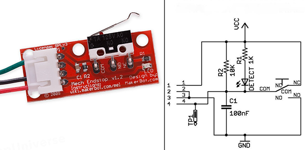
If you find yourself laying out a new revision, can you add support for powered end stops, these are very common on 3D printers and can be had for pennies, they include all the filters at the switch end and have an LED for confirming operation.
see: http://marlinfw.org/assets/images/docs/hardware/endstops/makerbot_endstop.png
The only requirement, is to add an extra +5v pin on the end-stop pin-outs, so that each end-stop row has
[Signal] - [Grnd] - [Vcc] as per the RAMPS cards
Typical prices are very very low.
here is a listing from my region, but these devices can be found everywhere
the price here for 6 pre-wired end-stops is about $3
I am Using V1.2.1 on an MPCNC using the latest grbl esp32 firmware with the mpcnc_laser_module_ v1p2.h machine. I am using JTech 2.8W laser and I am having issues with the PWM output. When I read the voltage across the PWM pins and NO wires attached to these pins, with M3S1000 command, I read 5v but when I attach the JTech driver board to these pins then the voltage drops to around 2.6v with the same M3S1000 command. Has anyone else had this issue or know what the cause for it is?
Repeated the grbl_esp 32_cnc_controller v1.2.1 Board. I Use a CNC engraver with the ability to connect a milling cutter and a laser. When using the relay to switch the router in the firmware we use pin 2 and the string
#define USE_SPINDLE_RELAY
to connect the laser to the PWM we use pin 17 and a string
//#define USE_SPINDLE_RELAY
Is it possible to configure the firmware so that the PWM is sent to pin 17, and the relay connected to pin 2 switched the relay simultaneously, without updating the esp32 firmware?
changing the parameter $32 (laser mode) changes only the strategy of switching on the relay, but not its pin.
This is important for combined processing on CNC machines. Thank you for any help.
FYI: There is a new revision of the controller (V1.2.1). It only has minor changes and uses the same cpou map as V1.2
I am trying to get the homing/squaring functions sorted out but am having some issues. (I am only working with one axis at a time, in this case, the X-axis.) I have the steppers and limit switches wired up - movement to home is in the +X axis. When I click on the Home X, the steppers run, the limit switches both trigger, but only one side will back off and reset the switch. The other side will attempt to move in the +X direction and not back off from the closed limit switch. (The switches are wired as NC, so when closed, a continuity check shows no signal.) Any insights on what I'm doing wrong or where my configuration needs adjustment would be appreciated.
I got this far with this whole project (homing, plotting, ..), but I couldn't figure out how to enable/disable the spindle relay in grblesp. USE_SPINDLE_RELAY is defined in mpcnc_v1p2.h, but whatever M-code I use, the relay does not respond. It must be something stupid and simple...
thanks for any quick help
Hi, thanks for this design.
I've just pushed the button for an order from JLCPCB then noticed J3 doesn't allow for separate limit switches for separate motors on X and Y axes? Does Grbl allow for this? I was hoping to run this board on a V1 Engineering Lowrider where separate minimum limit switches for each of the two X axis rails to allow for autosquaring (and same on Z min).
Am I talking nonsense? Or does Grbl (unlike Marlin) not allow for two limit switches for each X motor?
Hi, there is an issue at the BOM "BOM_MPCNC Vp1p2p2.xlsx"
Transistor Q1 is the wrong type.
BOM_MPCNC Vp1p2p2.xlsx --> Q1 == BCV26 (PNP)
MPCNC_V1P2P1_bom.csv --> Q1 == MMBT9013H (NPN)
Hello,
Since a really great product.
Is it possible to buy the controller from eu. Shipping is quite expensive from tindie.
Thank you
Hi, I am new to CNC and programming as well. I am trying to figure out how to use the probe to set zero prior to starting main program.
I have created a simple program that was given on V1 engineering:
G92 X0 Y0 Z0 ; Set Current position to 0, all axes
G00 Z5.0000 F500.0 ; Raise Z 5mm at 8.3mm/s to clear clamps and screws
G28 Z-60 F40 ; Home in order, w/zprobe
M00
G92 Z0.15 ; Account for probe thickness (set your thickness)
G00 Z5.0000 F500 ; Raise Z probe off off of surface
M00 ; pause for LCD button press
M03 S ; PID, set spindle speed
Challange1: During the G28 line the z-axis moves at a lot higher speed than F40.
Challange2: During the movement on G28 when the Prb pin connects to the ground Pin nothing happens.
Challange3: M03 does not engage the spindle relay.
I am wondering what I am doing wrong here.
Thank you
Apologies if this isn't the right place to ask this question.
I want to use grbl_esp32 to control an openbuilds ox CNC router that I'm building. It will need a single driver for x and z, and 2 drivers for Y. Also, not sure it's relevant, but I plan to use TMC2130 drivers, as I believe I'll need the additional current for my motors.
I found the grbl_ESP32_MPCNC controller card on tindie, and I think it can do what I want. I don't want to use auto-squaring or have a ganged x axis, so can I just comment out the extra x step pins and the x and y axis squaring in cpu_map.h?
#define USE_GANGED_AXES // allow two motors on an axis

  #define X_STEP_PIN      GPIO_NUM_12
  // #define X_STEP_B_PIN    GPIO_NUM_22  // ganged motor
  // #define X_AXIS_SQUARING

  #define Y_STEP_PIN      GPIO_NUM_14
  #define Y_STEP_B_PIN    GPIO_NUM_21  // ganged motor
  // #define Y_AXIS_SQUARING

  #define Z_STEP_PIN      GPIO_NUM_27

  #define X_DIRECTION_PIN   GPIO_NUM_26
  #define Y_DIRECTION_PIN   GPIO_NUM_25
  #define Z_DIRECTION_PIN   GPIO_NUM_33

  // OK to comment out to use pin for other features
  #define STEPPERS_DISABLE_PIN GPIO_NUM_13
I recently purchased one of your MPCNC boards and it is working well.
If I wanted to use the Y-axis as an A-Axis for rotation how would it be configured in GRBL ESP32
Would I be able to command angular degrees? and how would the feed rate be calculated if there was a linear and rotary movement on the same line?
Hey,
Please tell me how to properly connect the Stop button to this controller, the button itself is normal, connecting to the contact Pst, Srt and Hold do not give results? What am I doing wrong?
Thanks.
I just finished wiring the four X and Y steppers and limit switches for my MPCNC. When trying to move either axis, only the second of the motors for that axis move. So if I move the X axis, only X2 moves, Y2 for Y.
I swapped the motors and drivers (A4988) to make sure all the components work and they do. I also went ahead and recompiled the firmware as per the wiki with no change.
I unfortunately do not have an oscilloscope or logic analyser so I can't verify the board is sending steps to both motors.
Am I overlooking something?
In the next revision, could you provide support for more advanced stepper modules?
this would require that the three config pins have a way to set them individually or have them connect to spi (for the most advanced features)
If this could support the tmc2130 modules, you could potentially eliminate limit switches.
I'm thinking of a 3 pin jumper for each of the config pins, high, low (one side connected or removed) or spi (other side connected)
Hello,
Some time ago I was trying to find ESP 32 CNC shield to buy and I found your schematic on the GITHUB so I downloaded your schematic and made some changes in it for my personal purposes.
Can I ask you for checking my schematic if it will be compatibile with your firmware ?
https://github.com/linewallker/ESP-32-CNC-SHIELD-PORT
If not I understnad.
Thank you for any kind of answer.
Hello, I would buy the board, but after conversion and international shipping, it would cost $150 to send.
I would instead like to get the pcb printed and hand solder the components, but I do not know what file to send to the pcb fabricator.
is it the Gerber files?
https://github.com/bdring/Grbl_ESP32_MPCNC_Controller/tree/master/gerbers
if so, what is the latest? v1p2 or v1p2p1?
A declarative, efficient, and flexible JavaScript library for building user interfaces.
🖖 Vue.js is a progressive, incrementally-adoptable JavaScript framework for building UI on the web.
TypeScript is a superset of JavaScript that compiles to clean JavaScript output.
An Open Source Machine Learning Framework for Everyone
The Web framework for perfectionists with deadlines.
A PHP framework for web artisans
Bring data to life with SVG, Canvas and HTML. 📊📈🎉
JavaScript (JS) is a lightweight interpreted programming language with first-class functions.
Some thing interesting about web. New door for the world.
A server is a program made to process requests and deliver data to clients.
Machine learning is a way of modeling and interpreting data that allows a piece of software to respond intelligently.
Some thing interesting about visualization, use data art
Some thing interesting about game, make everyone happy.
We are working to build community through open source technology. NB: members must have two-factor auth.
Open source projects and samples from Microsoft.
Google ❤️ Open Source for everyone.
Alibaba Open Source for everyone
Data-Driven Documents codes.
China tencent open source team.