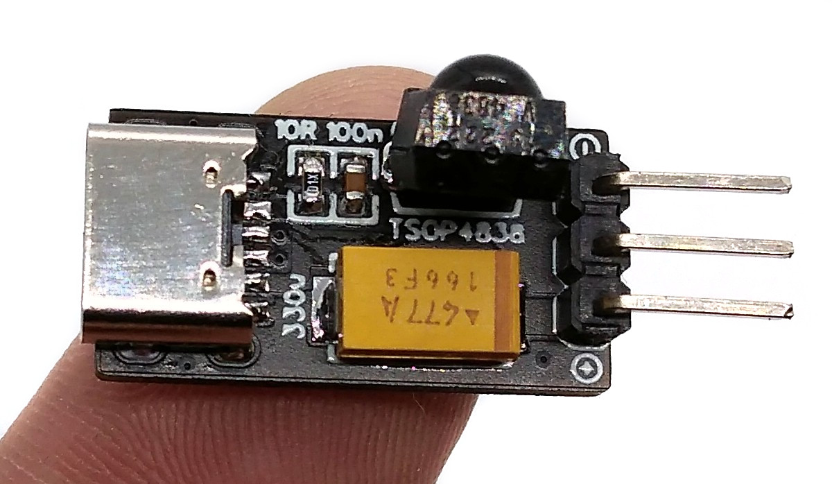
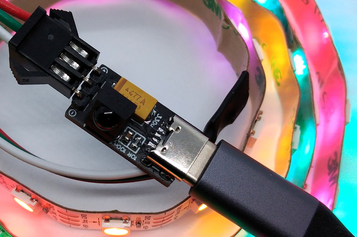
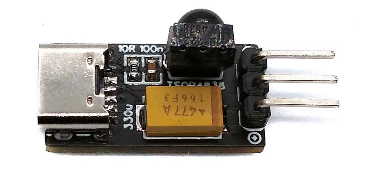
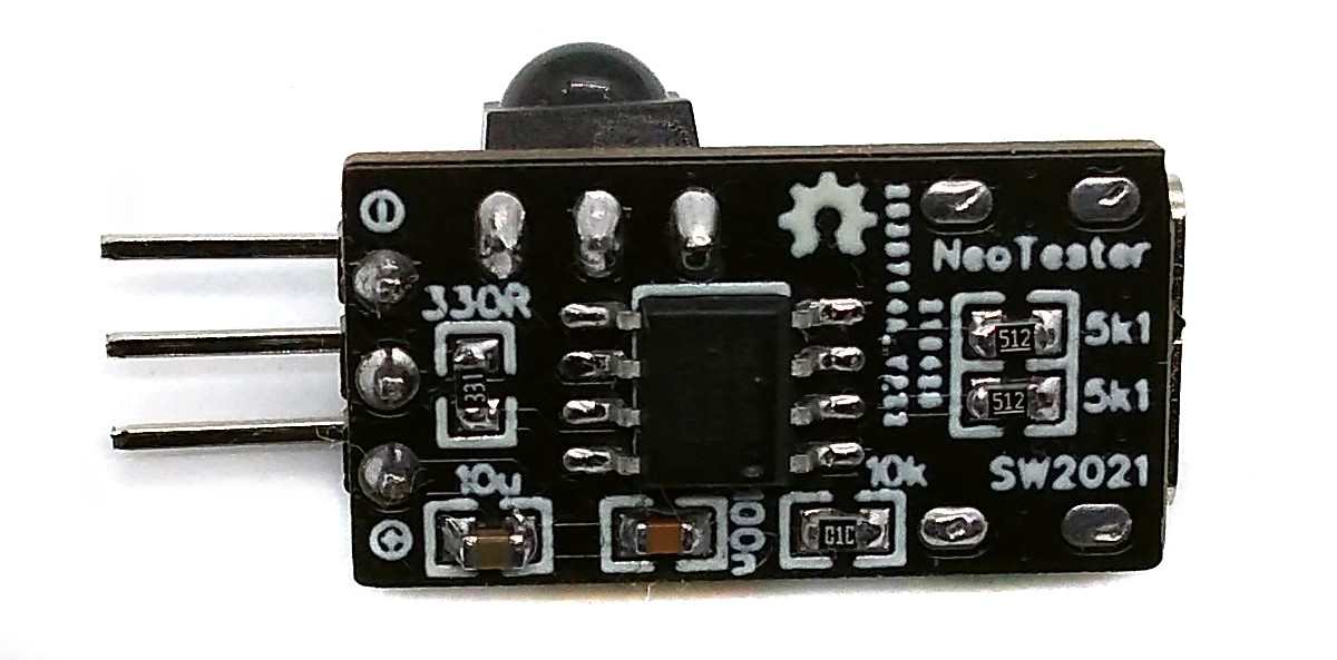
An ATtiny13 is more than sufficient to control almost any number of NeoPixels via an IR remote. The NeoController was originally developed as a tester for 800kHz NeoPixel strips. Since there was still so much flash left in the ATtiny13, an IR receiver was integrated so that some parameters can be controlled with an IR remote control. In this way, it is also suitable as a simple and cheap remote-controlled control unit for NeoPixels. Due to its small size (21.6mm x 11.4mm), it can be soldered directly to the LED strip without any problems. The power supply via a USB-C connection enables currents of up to 3A. There is still more than a third of the flash memory left for additional ideas.
- Project Video (YouTube): https://youtu.be/HLtST_1GFfo
- Design Files (EasyEDA): https://easyeda.com/wagiminator/attiny13-tinyneotester
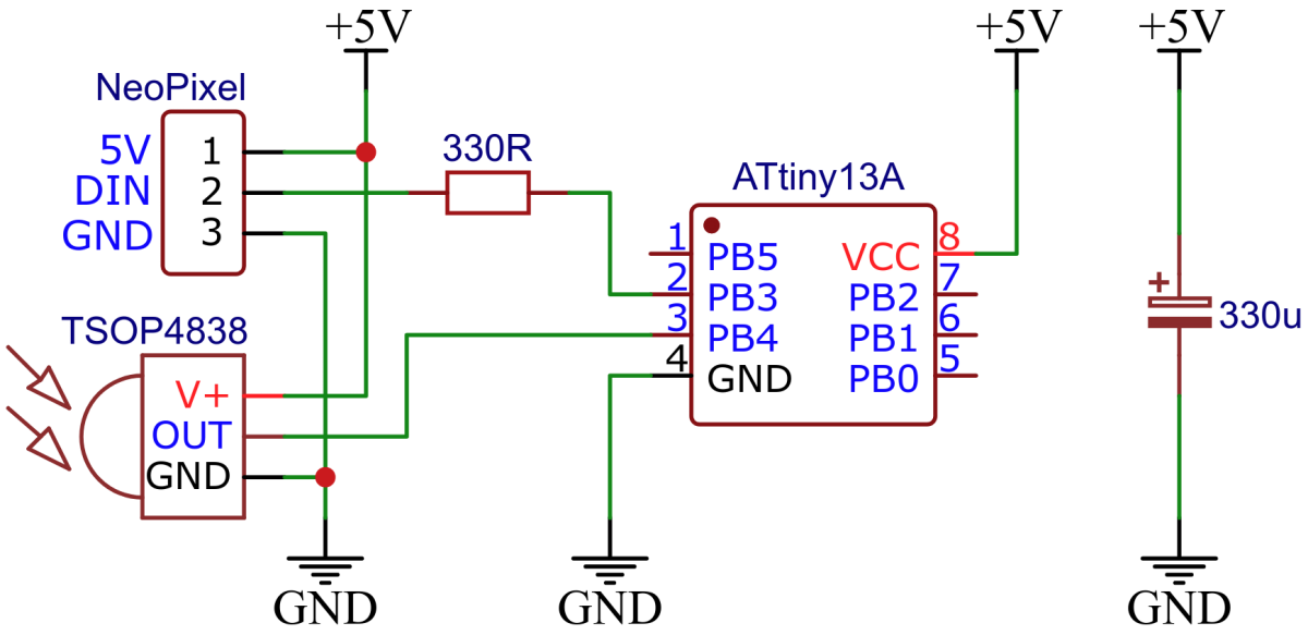
The wiring is pretty simple. For a breadboard test you can use the following simplified schematic:
The control of NeoPixels with 8-bit microcontrollers is usually done with software bit-banging. However, this is particularly difficult at low clock rates due to the relatively high data rate of the protocol and the strict timing requirements. The essential protocol parameters for controlling the WS2812 NeoPixels (or similar 800kHz addressable LEDs) can be found in the datasheet.
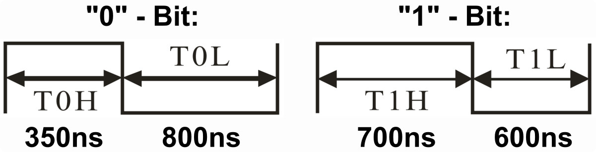
Fortunately, the timing is nowhere near as strict as the data sheet suggests. The following timing rules can be derived from the excellent articles by Josh Levine and Tim and should work with all 800kHz addressable LEDs:
| Pulse | Parameter | Min | Typical | Max |
|---|---|---|---|---|
| T0H | "0"-Bit, HIGH time | 65 ns | 350 ns | 500 ns |
| T0L | "0"-Bit, LOW time | 450 ns | 800 ns | 8500 ns |
| T1H | "1"-Bit, HIGH time | 625 ns | 700 ns | 8500 ns |
| T1L | "1"-Bit, LOW time | 450 ns | 600 ns | 8500 ns |
| TCT | Total Cycle Time | 1150 ns | 1250 ns | 9000 ns |
| RES | Latch, LOW time | 9 µs | 50 µs | 280 µs |
Apart from T0H, the maximum values can be even higher, depending on when the NeoPixels actually latch the sent data (with some types only after 280µs!). This also makes it possible to work without a buffer and thus without the use of SRAM, which is the prerequisite for being able to control so many pixels with an ATtiny13. The software essentially only has to ensure that T0H is a maximum of 500ns and T1H is at least 625ns, so that the pixels can reliably differentiate "0" from "1" and that the time between sending two bytes is less than the latch time. Assuming that the ATtiny13 runs with a clock frequency of 9.6 MHz, the following simple bit-banging function for the transmission of a data byte to the NeoPixels string was implemented:
// Send a byte to the pixels string
void NEO_sendByte(uint8_t byte) {               // CLK  comment
  for(uint8_t bit=8; bit; bit--) asm volatile(  //  3   8 bits, MSB first
    "sbi  %[port], %[pin]   \n\t"               //  2   DATA HIGH
    "sbrs %[byte], 7        \n\t"               // 1-2  if "1"-bit skip next instruction
    "cbi  %[port], %[pin]   \n\t"               //  2   "0"-bit: DATA LOW after 3 cycles
    "rjmp .+0               \n\t"               //  2   delay 2 cycles
    "add  %[byte], %[byte]  \n\t"               //  1   byte <<= 1
    "cbi  %[port], %[pin]   \n\t"               //  2   "1"-bit: DATA LOW after 7 cycles
    ::
    [port]  "I"   (_SFR_IO_ADDR(PORTB)),
    [pin]   "I"   (NEO_PIN),
    [byte]  "r"   (byte)
  );
}
When compiled, the function for bit-banging a data byte requires only 20 bytes of flash. Here is the resulting signal captured with a logic analyzer:
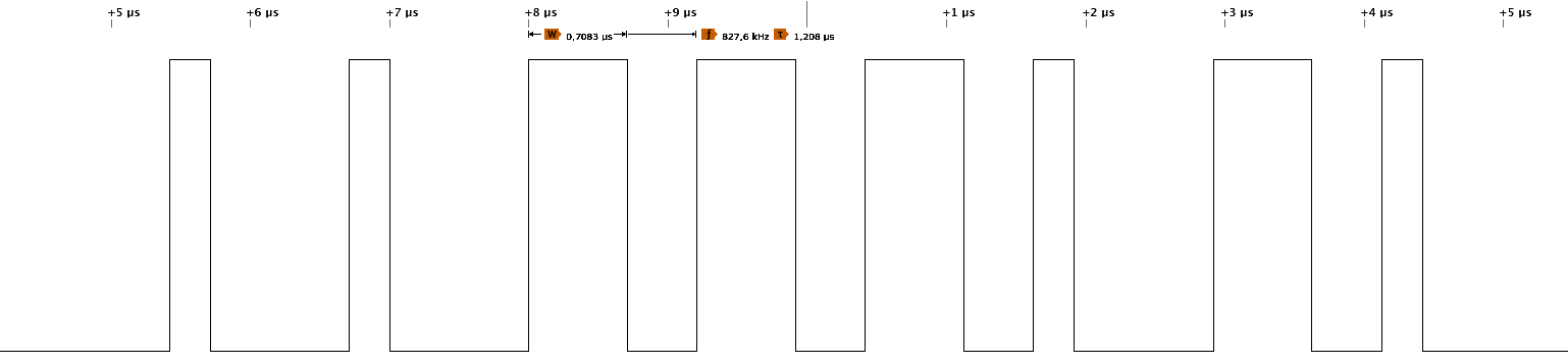
The resulting timing values are shown in the following table:
| Pulse | Parameter | Clock Cycles | Time |
|---|---|---|---|
| T0H | "0"-Bit, HIGH time | 3 Cycles | 313 ns |
| T0L | "0"-Bit, LOW time | 10 Cycles | 1042 ns |
| T1H | "1"-Bit, HIGH time | 7 Cycles | 729 ns |
| T1L | "1"-Bit, LOW time | 5 Cycles | 521 ns |
| TCT | Total Cycle Time | 13/12 Cycles | 1354/1250 ns |
This results in an average transfer rate of 768 kbps, at least for a single data byte. The implementation can certainly still be optimized in terms of speed, but this is already close to the maximum and safe within the limits even with an uncalibrated internal oscillator (you can push it to the max by replacing "rjump .+0" with "nop"). Remember that interrupts should be disabled during transmission, otherwise the timing requirements cannot be met.
There are three or four data bytes for each NeoPixel, depending on its type. These are transmitted with the most significant bit first in the order green, red and blue (GRB-type), red, green, blue (RGB-type) or red, green, blue, white (RGBW-type). The data for the NeoPixel, which is closest to the microcontroller, is output first, then for the next up to the outermost pixel. So this doesn't work like an ordinary shift register! After all color data have been sent, the data line must be kept LOW for at least 9 to 280µs (depending on the type of NeoPixel) so that the transferred data is latched and the new colors are displayed.
If the power supply allows this (consider that the board itself is only designed for a maximum of 3A), in principle much more than 255 pixels can be controlled. To do this, the corresponding counter variables must be expanded to 16 bits for up to 65,535 pixels or 32 bits for up to 4,294,967,295 pixels.
The IR receiver implementation requires 228 bytes of flash including decoding and error detection. Only the NEC protocol is supported, but this is used by almost all cheap IR remote controls. Alternatively, you can build such a remote control yourself with TinyRemote.
The NEC implementation works without timers and interrupts. Since the start burst of a NEC telegram lasts a full 9 ms, it is sufficient to poll the IR pin every now and then. When a start frame has been detected, the signal is then measured and decoded according to the NEC protocol. The program was tested with the TSOP4838, but it should also work with other 38kHz IR receivers (note different pinout if necessary).
The output of the IR reciever is inverted (active LOW), a burst is indicated by a LOW signal, a pause by a HIGH signal. IR message starts with a 9ms leading burst followed by a 4.5ms pause. Afterwards 4 data bytes are transmitted, least significant bit first. A "0"-bit is a 562.5µs burst followed by a 562.5µs pause, a "1"-bit is a 562.5µs burst followed by a 1687.5µs pause. A final 562.5µs burst signifies the end of the transmission. According to the data sheet of the TSOP4838, the length of the output signal differs from the transmitted signal by up to 158µs, which the code must take into account. The four data bytes are in order:
- the 8-bit address for the receiving device,
- the 8-bit logical inverse of the address,
- the 8-bit key-dependend command and
- the 8-bit logical inverse of the command.
The Extended NEC protocol uses 16-bit addresses. Instead of sending an 8-bit address and its logically inverse, first the low byte and then the high byte of the address is transmitted.
Here is an example signal captured with a logic analyzer:
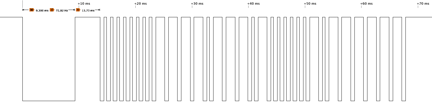
For a more detailed explanation on the NEC protocol refer to TinyRemote. Don't forget to define the used IR codes in the sketch!
// IR codes
#define IR_ADDR       0x1A    // IR device address
#define IR_POWER      0x01    // IR code for power on/off
#define IR_BRIGHT     0x02    // IR code for brightness
#define IR_SPEED      0x03    // IR code for animation speed
#define IR_DENSE      0x04    // IR code for color density
#define IR_FAIL 0xFF // IR fail codeThere are some firmware examples in the "software" folder:
| Firmware | Description |
|---|---|
| basic | A simple rainbow animation that can be controlled with the IR remote control in terms of brightness, animation speed and color density. |
| gamma | A similar rainbow animation but with gamma correction. |
| tiny10 | A similar implementation for the ATtiny10. |
Open the NeoController Sketch and adjust the IR codes so that they match your remote control. Remember that only the NEC protocol is supported. Also define the type of NeoPixel you are using (GRB, RGB or RGBW).
Since there is no ICSP header on the board, you have to program the ATtiny either before soldering using an SOP adapter, or after soldering using an EEPROM clip. The AVR Programmer Adapter can help with this.
The following instructions refer to the "basic" firmware.
- Make sure you have installed MicroCore.
- Go to Tools -> Board -> MicroCore and select ATtiny13.
- Go to Tools and choose the following board options:
- Clock: 9.6 MHz internal osc.
- BOD: BOD 2.7V
- Timing: Micros disabled
- Connect your programmer to your PC and to the ATtiny.
- Go to Tools -> Programmer and select your ISP programmer (e.g. USBasp).
- Go to Tools -> Burn Bootloader to burn the fuses.
- Open the NeoController sketch and click Upload.
- Make sure you have installed avrdude.
- Connect your programmer to your PC and to the ATtiny.
- Open a terminal.
- Navigate to the folder with the hex-file.
- Execute the following command (if necessary replace "usbasp" with the programmer you use):
avrdude -c usbasp -p t13 -U lfuse:w:0x3a:m -U hfuse:w:0xff:m -U flash:w:neocontroller.hex
- Make sure you have installed avr-gcc toolchain and avrdude.
- Connect your programmer to your PC and to the ATtiny.
- Open a terminal.
- Navigate to the folder with the makefile and the sketch.
- Run
PROGRMR=usbasp make installto compile, burn the fuses and upload the firmware (change PROGRMR accordingly).
- Connect the NeoPixel-String to respective pin header. Watch the correct pinout!
- Connect a 5V power supply to the USB-C socket.
- The NeoController should immediately start to show a rainbow animation.
- Use your IR remote control to change animation pattern or to switch on/off the NeoPixels.
- ATtiny13A datasheet
- WS2812 Datasheet
- TSOP4838 Datasheet
- Josh Levine's Article about NeoPixels
- Tim's Article about NeoPixels
- AdaFruit NeoPixel Überguide
- IR Receiver Implementation

This work is licensed under Creative Commons Attribution-ShareAlike 3.0 Unported License. (http://creativecommons.org/licenses/by-sa/3.0/)


