Notes accompanying the Robot Ignite Academy ROBOT CREATION WITH URDF Course https://www.robotigniteacademy.com/en/course/robot-creation-with-urdf-ros/details/
- In this unit, you will learn how to go from a physical robot to a visual virtual model. By visual, we understand that its not a physically working simulation model. It's only the barebones of what, at the end, will be used for simulation.
- But this URDF Visual model is already very useful.
- If you have a real robot and you want to use the ROS infrastructure, you need a virtual description of how the robot is connected and where each of the sensors is in some applications. For example, if you have a camera mounted on the head of the robot, through the virtual robot description (the URDF file ), you can use the TF ROS structure to know exactly where the camera is based by only the joint sensor readings.
It also allows you to represent the robot model inside RVIZ.
So, you will start by creating the URDF of the robot Mira.
- Learn how to use the URDF creation tools and the step-by-step procedure for creating a robot model.
- Learn about the morphology of the robot you want to work with.
- Obtain the 3D models that you will need in the correct format.
- Generate the link and joint structure.
- Test the movement of the joints.
So, let's get started.
- Let's create the URDF file in the appropriate ROS structure and let's create a ROS package for each robot model that you create.
- It's a common practice to always create a "my_robot_description" package where you store all of the files that describe the robot. You will find this robotname_description package everywhere in ROS packages that have robot models defined.
- So create a ROS package named
my_mira_description
cd /home/user/catkin_ws/src
catkin_create_pkg my_mira_description rospy rviz controller_manager gazebo_ros joint_state_publisher robot_state_publisher
Then create the following folders inside it:
- launch
- models
- rviz_config
- config
- urdf
- worlds
These folders are the ones that you will need to have a fully-functional simulated robot.
Now, create a URDF file called "mira.urdf" in the "urdf" folder
touch mira.urdfFor link there are three basic geometry shapes:
<cylinder radius="meters" length="meters"/>
<box size="x_length y_length z_length"/>
<sphere radius="meters"/>
For mira, we will only use <cylinder>
<?xml version="1.0"?>
<robot name="mira">
<!--URDF uses SI Units: meters, radians and kilograms-->

    <link
    name="base_link">
        <visual>
            <origin rpy="0 0 0" xyz="0 0 0"/>
            <geometry>
                <cylinder radius="0.06" length="0.09"/>
            </geometry>
        </visual>
    </link>

    <link
    name="roll_M1_link">
        <visual>
            <origin rpy="0 0 0" xyz="0 0 0"/>
            <geometry>
                <cylinder radius="0.06" length="0.09"/>
            </geometry>
        </visual>
    </link>

    <!--Joint types: revolute, continuous, prismatic, fixed, floating, planar-->
    <joint
    name="roll_joint" type="revolute">
        <parent link="base_link"/>
        <child link="roll_M1_link"/>
        <origin xyz="0.0023 0 -0.0005" rpy="0 0 0"/>
        <!--lower and upper are angle limits in radians-->
        <limit lower="-0.2" upper="0.2" effort="0.1" velocity="0.005"/>
        <!--1 0 0 Defines X as the axis of rotation-->
        <axis xyz="1 0 0"/>
    </joint>

</robot> In the example given, you have two links; in this case, two cylinders connected through a joint. Joints are what make elements of a robot turn and move. They are the articulations of the robot. The main elements to define in a joint are:
-
Type: there are these types: revolute, continuous, prismatic, fixed, floating, and planar. You can learn more here: http://wiki.ros.org/urdf/XML/joint. The joint selection will depend on how the physical model of your robot moves.
-
Parent and Child: Here is where you set who is connected to your link.
-
Origin: All of the coordinates and rpy are referenced to the Parent axis, not the child axis.
-
Limit: This is a very important element, especially when you have to control a robot movement.
-
Axis: Here you define around which Parent's AXIS the Child link will revolve. This, of course, depends on the type of joint; some of them don't have axis tags because they are irrelevant, such as the fixed joint.
To know how ROS will see the model and to help you position the links and joints, you will use the following urdf_visualize.launch
<launch>

     <!--USE: roslaunch my_mira_description urdf_visualize.launch model:='$(find myrobot_package)/urdf/myrobot.urdf' -->
    <arg name="model" default=""/>

    <!--Loads  URDF file to the param server variable "robot_description" -->
    <param name="robot_description" command="cat $(arg model)"/>
     <!--Second robot would need $ROBOT_2_DESCRIPTION and $MODEL_2 etc.-->

    <!--Start jointstate publisher & robotstate publisher. These publish the TFs of the URDF of the robot links and joints.-->
    <!--Send fake joint values-->
    <node pkg="joint_state_publisher" name="joint_state_publisher" type="joint_state_publisher">
        <param name="use_gui" value="TRUE"/>
    </node>
    <!--Combine joint values-->
    <node pkg="robot_state_publisher" name="robot_state_publisher" type="state_publisher" />

    <!--To launch rviz with a rviz config file-->
    <!--<node pkg="rviz" name="rviz" type="rviz" args="-d $(find pkg)/rviz_config/rviz_config_file.rviz"/>-->
    <node pkg="rviz" name="rviz" type="rviz" args="" />

</launch>
This command launches a totally empty RVIZ session, to which you will have to add the TF and RobotModel representations:
roslaunch my_mira_description urdf_visualize.launch model:='$(find my_mira_description)/urdf/mira.urdf'You will have to add two elements in RVIZ and Afterwards save the RVIZ file so that you don't have to do this adding every time you launch.
- RobotModel: In this case, just select the robot_description variable for the RobotDescription field.
- TF: It will turn green as soon as you select the correct fixed frame, in this case base_link.
NOTE: As you can see, you have RVIZ, but also a window with a slider. This slider allows you to move the joints. It's the JointStatePublisher Gui. This is vital for checking if the joints are correctly set in the URDF. It also allows you to see if the given limits in the joints are the correct ones. If you can't see the "joint control" window, it must be behind the RVIZ window. Just move it around and, to avoid any further loss, right click on it and select in Layers>Always On Top.
Now that we have an Rviz Config file, we can include it in urdf_visualize.launch:
<!--To launch rviz with a rviz config file-->
<!--<node pkg="rviz" name="rviz" type="rviz" args="-d $(find pkg)/rviz_config/rviz_config.rviz"/>-->
<node pkg="rviz" name="rviz" type="rviz" args="-d $(find my_mira_description)/rviz_config/urdf.rviz" />
You can also see the Link-Joint structure of any URDF file through the urdf_to_graphiz tool:
$ roscd my_mira_description/urdf
$ urdf_to_graphiz mira.urdf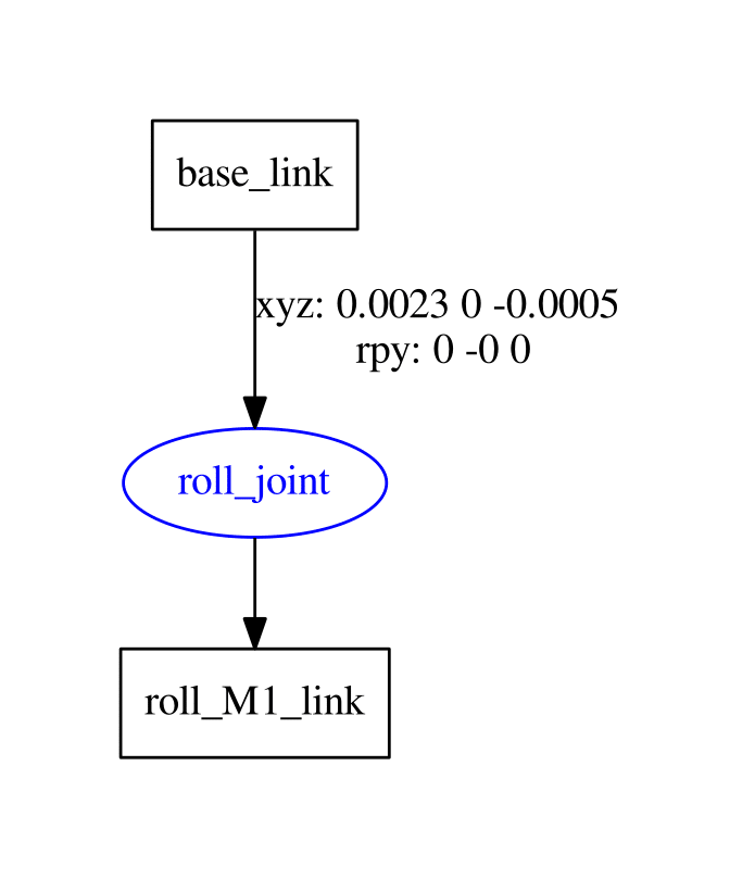
It's based on the xyz axis of the parent frame; in this case, it's the absolute world frame because it's the first link in the URDF file.
X = RED color AXIS,
Y = GREEN color AXIS, and
Z = BLUE color AXIS.
As for the rpy (Roll, Pitch, and Yaw ), it's also the parent's axis that corresponds to
Roll = Rotation in the X axis,
Pitch = Rotation in the Y axis, and
Yaw = Rotation in the Z axis.
he most important step in the creation of a URDF is knowing how the real robot moves.
You have to decide which type of joints it has and how all of the pieces are linked together.
In the simulation, you don't always have to mimic the exact way a robot works because you can simplify, as you do not have physical limitations.


This system emulates the real system, giving Roll, Pitch, and Yaw Movements.
- The Roll link connects to the base_link and rotates around the X axis.
- The Pitch link connects to the base_link and rotates around the Y axis.
- The Yaw link connects to the base_link and rotates around the Z axis.
Using the colors that match the axis helps a lot to keep the rotating axis clear. So bear that in mind when you define these kind of links.
These joints will also be the ones that are actuated when we introduce the actuators and controls in the simulation.
Note that we could have positioned the Yaw link in the center, but it's positioned in that way to be easy to see, and to slightly emulate the real system.
<?xml version="1.0"?>
<robot name="mira">
    <material name="blue">
        <color rgba="0 0 0.8 1"/>
    </material>
    <material name="red">
        <color rgba="0.8 0 0 1"/>
    </material>
    <material name="green">
        <color rgba="0 0.8 0 1"/>
    </material>
    <material name="grey">
        <color rgba="0.75 0.75 0.75 1"/>
    </material>
    <material name="white">
        <color rgba="1.0 1.0 1.0 1"/>
    </material>
    <material name="black">
        <color rgba="0 0 0 1"/>
    </material>

    <link
    name="base_link">
        <visual>
            <origin xyz="0 0 0" rpy="0 0 0"/>
            <geometry>
                <cylinder radius="0.06" length="0.09"/>
            </geometry>
            <material name="grey"/>
        </visual>
    </link>

     <!--Joint types: revolute, continuous, prismatic, fixed, floating, planar-->
    <joint
    name="roll_joint" type="revolute">
        <parent link="base_link"/>
        <child link="roll_M1_link"/>
        <origin xyz="0.0023 0 -0.0005" rpy="0 0 0"/>
        <!-- lower and upper are angle limits in radians -->
        <limit lower="-0.2" upper="0.2" effort="0.1" velocity="0.005"/>
        <!-- 1 0 0 Defines X as the axis of rotation -->
        <axis xyz="1 0 0"/>
    </joint>

    <link
    name="roll_M1_link">
        <visual>
            <origin xyz="0 0 0" rpy="0 0 0"/>
            <geometry>
                <cylinder radius="0.01" length="0.005"/>
            </geometry>
            <material name="red"/>
        </visual>
    </link>

    <joint
    name="pitch_joint" type="revolute">
        <parent link="roll_M1_link"/>
        <child link="pitch_M2_link"/>
        <origin xyz="0 0 0" rpy="0 -1.5708 0"/>
        <limit lower="0" upper="0.44" effort="0.1" velocity="0.005"/>
        <axis xyz="0 1 0"/>
    </joint>

    <link
    name="pitch_M2_link">
        <visual>
            <origin rpy="0 0 0" xyz="0 0 0"/>
            <geometry>
                <cylinder radius="0.01" length="0.005"/>
            </geometry>
            <material name="green"/>
        </visual>
    </link>

    <joint
    name="yaw_joint" type="continuous">
        <parent link="pitch_M2_link"/>
        <child link="yaw_M3_link"/>
        <origin xyz="0.01 0" rpy="0 1.5708 0"/>
        <limit effort="0.1" velocity="0.01"/>
        <axis xyz="0 0 1"/>
    </joint>

    <link
    name="yaw_M3_link">
        <visual>
            <origin xyz="0 0 0" rpy="0 0 0"/>
            <geometry>
                <cylinder radius="0.01" length="0.005"/>
            </geometry>
            <material name="blue"/>
        </visual>
    </link>

    <joint
    name="base_head_joint" type="fixed">
        <parent link="yaw_M3_link"/>
        <child link="head_link"/>
        <origin xyz="0 0 0" rpy="0 0 0"/>
    </joint>

    <link
    name="head_link">
        <visual>
            <origin xyz="0 0 0" rpy="0.0 0 0"/>
            <geometry>
                <sphere radius="0.06"/>
            </geometry>
            <material name="white"/>
        </visual>
    </link>

    <joint
    name="head_lefteye_joint" type="fixed">
        <parent link="head_link"/>
        <child link="left_eye_link"/>
        <origin xyz="0.0095 0.057 0.0085" rpy="-1.5708 0 0"/>
    </joint>

    <link
    name="left_eye_link">
        <visual>
            <origin rpy="0.0 0 0" xyz="0 0 0"/>
            <geometry>
                <cylinder radius="0.00525" length="0.00525"/>
            </geometry>
            <material name="black"/>
        </visual>
    </link>

    <joint
    name="head_righteye_joint" type="fixed">
        <parent link="head_link"/>
        <child link="right_eye_link"/>
        <origin xyz="-0.0095 0.057 0.0085" rpy="-1.5708 0 0"/>
    </joint>

    <link
    name="right_eye_link">
        <visual>
            <origin rpy="0.0 0 0" xyz="0 0 0"/>
            <geometry>
                <cylinder radius="0.00525" length="0.00525"/>
            </geometry>
            <material name="black"/>
        </visual>
    </link>

    <joint
    name="head_camera_joint" type="fixed">
        <parent link="head_link"/>
        <child link="camera_link"/>
        <origin xyz="0 0.057 0.0255" rpy="0 0 0"/>
    </joint>

    <link
    name="camera_link">
        <visual>
            <origin xyz="0 0 0" rpy="0 0 0"/>
            <geometry>
                <box size="0.0005 0.0005 0.0005"/>
            </geometry>
            <material name="green"/>
        </visual>
    </link>

</robot>
And now looks like this:

Naturally, one of the most difficult aspects was probably positioning the elements.
That's why it's so important to iterate step by step, and if possible, have all of the assembly measurements in blueprints, like this one:

This was taken from the Solid Works model of the Gurdy Robot from later in the course.
It's highly advisable to have a CAD model fully assembled to be able to get precise measurements on how the joints have to be positioned. Otherwise, it's an iterative slow process.
This is a very wide topic and there are many ways of doing it. Here you will learn just the basic elements needed for correctly importing 3D models.
- When using a CAD tool, the final models have to be saved in STL format or Dae format. SolidWorks, for example, gives the option of STL. The only advantage with DAE is that DAE saves color information. But that's something that can be added afterwards in Blender.
- Import the STL of the DAE models into Blender. Here you will have to set the origin of the model and the units. This is absolutely vital. The setting of the axis will determine how difficult it is to create the URDF model. As for the units, having a 10-foot high Mira Robot is not very realistic, apart from the effects on the inertias afterwards.
- Once you have the axis and units set up, you can add a material to the blender model to add color.
- Once done, you export it to dae format. Sometimes, blender doesn't save properly the first time, so you will have to import the new dae into blender again in an empty scene and then export it again to dae.
Good resources are:
For this tutorial, the meshes were provided in catkin_ws/src/my_mira_description/models/mira/meshes/
mira_body_v3.dae
mira_eye_v4.dae
mira_head_v5.dae
So all that needs to be done is to replace the geometry that are now spheres, cylinders, and so on by the .dae files like:
<link name="head_link">
...
    <!-- <sphere radius="0.06"/> -->
    <mesh filename="package://my_mira_description/models/mira/meshes/mira_head_v5.dae"/>
...
</link>
And also the physical properties will need to be adjusted using Gazebo's syntax like:
<!-- This is for color and physical properties in Gazebo, color won't work with the material tag in gazebo
    only for URDF coloring -->
    <gazebo reference="roll_M1_link">
        <kp>1000.0</kp>
        <kd>10.0</kd>
        <mu1>10.0</mu1>
        <mu2>10.0</mu2>
        <material>Gazebo/Red</material>
    </gazebo>
The full file will look like:
<?xml version="1.0"?>
<robot name="mira">
    <material name="blue">
        <color rgba="0 0 0.8 1"/>
    </material>
    <material name="red">
        <color rgba="0.8 0 0 1"/>
    </material>
    <material name="green">
        <color rgba="0 0.8 0 1"/>
    </material>
    <!-- <material name="grey">
        <color rgba="0.75 0.75 0.75 1"/>
    </material>
    <material name="white">
        <color rgba="1.0 1.0 1.0 1"/>
    </material>
    <material name="black">
        <color rgba="0 0 0 1"/>
    </material> -->

    <link
    name="base_link">
        <visual>
            <origin xyz="0 0 0" rpy="0 0 0"/>
            <geometry>
                <!-- <cylinder radius="0.06" length="0.09"/> -->
                <mesh filename="package://my_mira_description/models/mira/meshes/mira_body_v3.dae"/>
            </geometry>
            <material name="grey"/>
        </visual>
    </link>

     <!--Joint types: revolute, continuous, prismatic, fixed, floating, planar-->
    <joint
    name="roll_joint" type="revolute">
        <parent link="base_link"/>
        <child link="roll_M1_link"/>
        <origin xyz="0.0023 0 -0.0005" rpy="0 0 0"/>
        <!--lower and upper are angle limits in radians-->
        <limit lower="-0.2" upper="0.2" effort="0.1" velocity="0.005"/>
        <!--1 0 0 Defines X as the axis of rotation-->
        <axis xyz="1 0 0"/>
    </joint>

    <link
    name="roll_M1_link">
        <visual>
            <origin xyz="0 0 0" rpy="0 0 0"/>
            <geometry>
                <cylinder radius="0.01" length="0.005"/>
            </geometry>
            <material name="red"/>
        </visual>
    </link>

    <!-- This is for color and physical properties in Gazebo, color won't work with the material tag in gazebo
    only for URDF coloring -->
    <gazebo reference="roll_M1_link">
        <kp>1000.0</kp>
        <kd>10.0</kd>
        <mu1>10.0</mu1>
        <mu2>10.0</mu2>
        <material>Gazebo/Red</material>
    </gazebo>

    <joint
    name="pitch_joint" type="revolute">
        <parent link="roll_M1_link"/>
        <child link="pitch_M2_link"/>
        <origin xyz="0 0 0" rpy="0 -1.5708 0"/>
        <limit lower="0" upper="0.44" effort="0.1" velocity="0.005"/>
        <axis xyz="0 1 0"/>
    </joint>

    <link
    name="pitch_M2_link">
        <visual>
            <origin rpy="0 0 0" xyz="0 0 0"/>
            <geometry>
                <cylinder radius="0.01" length="0.005"/>
            </geometry>
            <material name="green"/>
        </visual>
    </link>

    <!-- This is for color and physical properties in Gazebo, color won't work with the material tag in gazebo
    only for URDF coloring -->
    <gazebo reference="pitch_M2_link">
        <kp>1000.0</kp>
        <kd>10.0</kd>
        <mu1>10.0</mu1>
        <mu2>10.0</mu2>
        <material>Gazebo/Green</material>
    </gazebo>

    <joint
    name="yaw_joint" type="continuous">
        <parent link="pitch_M2_link"/>
        <child link="yaw_M3_link"/>
        <origin xyz="0.01 0" rpy="0 1.5708 0"/>
        <limit effort="0.1" velocity="0.01"/>
        <axis xyz="0 0 1"/>
    </joint>

    <link
    name="yaw_M3_link">
        <visual>
            <origin xyz="0 0 0" rpy="0 0 0"/>
            <geometry>
                <cylinder radius="0.01" length="0.005"/>
            </geometry>
            <material name="blue"/>
        </visual>
    </link>

    <!-- This is for color and physical properties in Gazebo, color won't work with the material tag in gazebo
    only for URDF coloring -->
    <gazebo reference="yaw_M3_link">
        <kp>1000.0</kp>
        <kd>10.0</kd>
        <mu1>10.0</mu1>
        <mu2>10.0</mu2>
        <material>Gazebo/Blue</material>
    </gazebo>

    <joint
    name="base_head_joint" type="fixed">
        <parent link="yaw_M3_link"/>
        <child link="head_link"/>
        <origin xyz="0 0 0" rpy="0 0 0"/>
    </joint>

    <link
    name="head_link">
        <visual>
            <origin xyz="0 0 0" rpy="0.0 0 0"/>
            <geometry>
                <!-- <sphere radius="0.06"/> -->
                <mesh filename="package://my_mira_description/models/mira/meshes/mira_head_v5.dae"/>
            </geometry>
            <!-- <material name="white"/> -->
        </visual>
    </link>

    <joint
    name="head_lefteye_joint" type="fixed">
        <parent link="head_link"/>
        <child link="left_eye_link"/>
        <origin xyz="0.0095 0.057 0.0085" rpy="-1.5708 0 0"/>
    </joint>

    <link
    name="left_eye_link">
        <visual>
            <origin rpy="0.0 0 0" xyz="0 0 0"/>
            <geometry>
                <!-- <cylinder radius="0.00525" length="0.00525"/> -->
                <mesh filename="package://my_mira_description/models/mira/meshes/mira_eye_v4.dae"/>
            </geometry>
            <!-- <material name="black"/> -->
        </visual>
    </link>

    <joint
    name="head_righteye_joint" type="fixed">
        <parent link="head_link"/>
        <child link="right_eye_link"/>
        <origin xyz="-0.0095 0.057 0.0085" rpy="-1.5708 0 0"/>
    </joint>

    <link
    name="right_eye_link">
        <visual>
            <origin rpy="0.0 0 0" xyz="0 0 0"/>
            <geometry>
                <!-- <cylinder radius="0.00525" length="0.00525"/> -->
                <mesh filename="package://my_mira_description/models/mira/meshes/mira_eye_v4.dae"/>
            </geometry>
            <!-- <material name="black"/> -->
        </visual>
    </link>

    <joint
    name="head_camera_joint" type="fixed">
        <parent link="head_link"/>
        <child link="camera_link"/>
        <origin xyz="0 0.057 0.0255" rpy="0 0 0"/>
    </joint>

    <link
    name="camera_link">
        <visual>
            <origin xyz="0 0 0" rpy="0 0 0"/>
            <geometry>
                <box size="0.0005 0.0005 0.0005"/>
            </geometry>
            <material name="green"/>
        </visual>
    </link>

    <gazebo reference="camera_link">
        <material>Gazebo/Green</material>
    </gazebo>

</robot>