Git Product home page Git Product logo

fu-dyson-bms's Introduction

FU-Dyson-BMS

An (Unofficial) Firmware Upgrade for Dyson V6/V7 Vacuum Battery Management System (BMS)

Github Header Image


Dyson vacuum batteries are designed to fail.

Here's why:

  1. Series battery cells in a battery pack inevitably become imbalanced. This is extremely common and why cell balancing was invented.
  2. Dyson uses a very nice ISL94208 battery management IC that includes cell balancing. It only requires 6 resistors that cost $0.00371 each, or 2.2 cents in total for six. 1
  3. Dyson did not install these resistors. (They even designed the V6 board, PCB 61462, to support them. They just left them out.)
  4. Rather than letting an unbalanced pack naturally result in lower usable capacity, when the cells go moderately (300mV) out of balance (by design, see step 3) Dyson programmed the battery to stop working...permanently. It will give you the 32 red blinks of death and will not charge or discharge again. It could not be fixed. Until now. 2

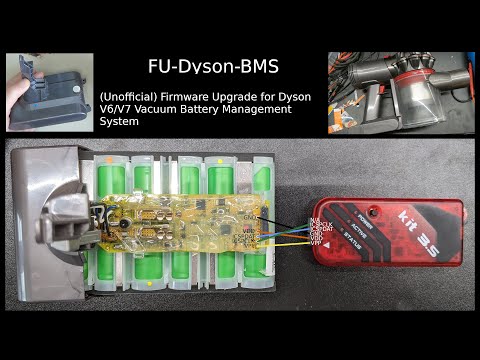
FU-Dyson-BMS is a replacement firmware for the microcontroller inside Dyson V6/V7 vacuum batteries. By using this firmware, your battery pack will not become unusable if the cells become imbalanced, you will just have reduced battery capacity as usual. It will also allow you to replace the battery cells to repair your battery, rather than be forced to replace it.

Demonstration, disassembly, and programming video:

https://www.youtube.com/watch?v=dwyA5rBjncg

FU-Dyson-BMS - (Unofficial) Firmware Upgrade for Dyson V6/V7 Vacuum Battery Management System

Revolutionary features:

  • Cell balance LED indicator
  • State of charge LED indicator
  • Robust fault handling and logging
  • Total runtime tracking
  • Can be run in debug mode for near-real-time diagnostics
  • Doesn't brick itself!
  • Doesn't generate e-waste and try to take your money when your cells go out of balance!

Why you would want this:

  • You want to vacuum your apartment but your cells became slightly out of balance because you left the vacuum off the charger for too long and now your vacuum doesn’t work (ask me how I know)
  • You want to replace a bad cell in your battery pack
  • You want to understand what your battery is doing and why.
  • You don’t like feeling like a cash cow being squeezed for all you’re worth.

Compatible vacuums/batteries:

  • Dyson V7 - Model SV11 - PCB 279857 - Compatible + Tested

  • Dyson V7 - Model ?? - PCB 228499 - Reported Working by NemoLee

  • Dyson V6 - Model SV04/SV09 - PCB 61462 - Compatible + Tested

  • Dyson V6 - Model SV04 - PCB 188002 - Compatible + Tested

Note: the model numbers are kind of weird. There are three different ways to identify/categorize your vacuum:

  1. The advertised version number (V6, V7, etc)
  2. The actual model number printed on the battery (SV04, SV09, SV11)
  3. The part number printed on the battery PCB (61462, 279857, 188002).

Some models like SV04 contain different versions of the battery PCB. Many of these PCB versions are extremely similar and I have no idea why Dyson seems to have made at least 5 different versions. I recommend you use the PCB part number for reference if possible, or the model number printed on the battery otherwise. I still use the V6, V7 names in some places since that is what most people are familiar with, and I keep changing my mind as to which identification method is better.

Probably not compatible: (Although it’d be interesting to see PCB photos of them to be sure)

  • V10 vacuums
  • V11 vacuums
  • Anything newer

If you aren’t sure if your battery is compatible, please submit a Github issue with the highest quality photos possible of the battery PCB and provide the advertised model number (V6, V7, etc) and printed model number (SV09, SV11, etc) and I’ll try to tell you if it will work.

How to install it:

Warning: The firmware flash process is irreversible. It is not possible to restore the factory firmware.

Summary:

  1. Be careful. Li-ion batteries are no joke and must be respected. You're working on a live battery pack that can output 100+ Amps if short-circuited.
  2. Disassemble battery pack to access PCB
  3. Make sure all cells are charged above 3V and that the pack LEDs do something when you press the button (with magnet on reed switch if using V7). This confirms the 3.3V rail is regulating and the PIC is awake/working.
  4. Remove conformal coating over programming connection points (if applicable)
  5. Connect PICkit to computer and, if you using a PICkit 3 or clone, install the PICkit 3 Programmer App and Scripting Tool v3.10. (https://www.microchip.com/en-us/tools-resources/archives/mplab-ecosystem)
  6. Connect PICkit to BMS board as shown below:
    (Note: I now recommend not connecting the VDD wire at all. The ISL94208 chip seems keen to fail with an externally supply voltage. I'd still suggest waking up the battery pack as describe in step 6 to power the board up for programming. One user has suggested (#24) even this may be unnecessary though.)
  7. Wake up battery pack by pressing button and placing magnet on reed switch (if using V7 vacuum).
  8. While maintaining tension on wires to BMS board, make sure PICkit can see the PIC16LF1847 microcontroller, then import and write the hex file from the latest GitHub release.


    For more details, see video linked at the top (https://www.youtube.com/watch?v=dwyA5rBjncg).


Disclaimer: Lithium-ion batteries can be dangerous and must be respected. Proper cell balancing may reduce this danger which is why only trained professionals who implement cell balancing according to the manufacturer recommended best practices should work on them...wait...well that doesn't include Dyson either so I guess we're on our own. According to the internet, they can spontaneously catch fire, burn your house down, drain your retirement fund, and run away with your wife. Consider yourself warned, and please don't sue me if something goes wrong because I assume no liability and provide no warranty. See section 15 and 16 of the COPYING file for more details.

Miscellaneous Thoughts on Repairing a Battery Pack

Battery Cell Connections and Measurement Points If you left your battery in storage for a long time, you may have found it no longer turns on at all and won’t charge either. This is because the battery cells have self-discharged so low that the ISL94208 won’t even turn on, which means the microcontroller won’t turn on either.

If you connect a constant current power supply directly to the terminals of the battery pack bypassing the BMS board, you can slowly recharge the cells until they are back within a normal voltage range (above 3V). I've found the PCBite probes to work well for easily connecting any cell or pack to a bench power supply. Soldering small wires to the nickel strips or jamming on alligator clips somehow would probably work too. I recommend charging at 50-100mA until all cells are over 3V. For safety, you don’t want to charge a battery that’s been depleted too far at the normal charge current (700mA).

After all cells are above 3V, the BMS should power up as usual. If you aren’t getting the 32 red blinks of death, you might not even need to install this firmware (as much as it pains me to admit it). While you have the battery disassembled, I’d recommend making sure all the battery cells are within 100mV of each other, and manual charge the lower cells to get them in that range.

Note: When charging cells that have been over-discharged, you should monitor them carefully to make sure they are taking a charge (the voltage is actually increasing), they aren't getting hot, and the cell voltages are gradually moving in to an acceptable range. Even if some of your cells are extremely out of balance, don't worry about that until you get them all above 3V. Having one cell at 1V and another at 2V might look really bad, but when they are back in range, they might look more like 3.1V and 3.2V.

If your battery isn’t turning on at all, do the following (do not leave unattended while charging):

  1. Disassemble your battery pack.
  2. Measure the voltage of all of the battery cells. You’ll probably find one or many are below 3V.
    • If your cells are all within 1V of each other and none are negatively charged: Using a bench power supply, charge the entire pack directly across the two large metal terminals that come off cell 1 and cell 6 and connect to the BMS board. This will bypass the BMS and charge the cells directly. Charge at 50-100mA constant current, with a voltage limit of 20V.
    • If your cells are more than 1V from each other: Use a bench power supply to charge the low cells individually to match the higher cells. Then charger the entire pack directly as mentioned in the previous bullet point.
    • If any cells are reverse charged, meaning they have a negative voltage where it should normally be positive, you’ll probably need to replace that battery cell. This would involve cutting the nickel strips connected to it, removing it from the battery pack, and spot welding in a new cell. This is beyond the scope of this documentation.

What do the LEDs mean?

While pulling trigger:

  • Red-Green-Blue flashes - Looks fancy and indicates you’re running the custom firmware
  • Solid Blue - The vacuum is on / Power output is enabled
  • 3x Blue flashes - Battery low (Low voltage cutoff reached).
    • Output disabled until charger connected or pack goes to sleep and forgets

When you release the trigger:

  • Green flashes - (Rough) Remaining Battery Capacity
    • Indicates (roughly) the remaining battery capacity on a scale of 1-6 flashes, with 6 being completely full and 1 being effectively empty.
    • 1 flash = 3.0V < Min cell < 3.2V
    • 2 flashes = 3.2V < Min cell < 3.4V
    • 3 flashes = 3.4V < Min cell < 3.6V
    • 4 flashes = 3.6V < Min cell < 3.8V
    • 5 flashes = 3.8V < Min cell < 4.0V
    • 6 flashes = 4.0V < Min cell < 4.2V
    • (Min cell means the voltage of whatever battery cell has the lowest voltage)
    • (Why 1-6 flashes? Well if 0 flashes was an option, you couldn't tell if the battery meter function was working at all or not)
    • Due to the current draw of the vacuum and the ESR of the cells, 3 flashes could probably be considered almost dead.

When you connect the charger:

  • Yellow flashes - Cell Balance Indicator
    • Indicates how out of balance your battery pack is.
    • Represents the voltage difference between your highest and lowest voltage cell.
    • Each flash = 50mV
    • Example: The highest voltage cell in your pack is 3.95V. The lowest voltage cell is 3.62V. 3.95V - 3.62V = 330mV difference. 330mv / 50mv per flash = 7 flashes (6.6 rounded to 7)
  • Solid blue - Charging is active
  • Solid white - Charging pause/wait
    • The highest voltage cell reached 4.2V so charging was disabled
    • It will wait for 70 seconds to let the battery cells recover a bit and then resume charging.
  • Solid green - Charging is complete/Idle
    • Once it takes less than 10 seconds of charging (blue LED) to reach the max cell voltage of 4.2V, charging will be marked as complete
    • Will sleep after 30 seconds of no activity

When you disconnect the charger:

  • Yellow flashes - Cell Balance Indicator
    • (See entry under "When you connect the charger")

When you hold down the trigger and connect the charger:

  • White flashes - Firmware version
    • One white flash = version 1. Four white flashes = version 4, etc
    • Charging will resume as normal after this is shown.

At any time:

  • Solid green - Battery pack is idle. The output isn't enabled and it isn't charging.
    • Will sleep after 30 seconds of no activity
  • Red flashes - Fault indicator/Error code
    • How you should handle errors: Make note of how many flashes are in your error code, make sure the charger is removed and trigger is released, and then wait 60 seconds for the error code to clear. Then you can try again if you want.

What do the error codes mean?

Number of Red Flashes Fault Name Fault Meaning Default Limit
4 ISL_INT_OVERTEMP_FLAG ISL94208 asserted flag that it reached the internal over-temperature limit 125C
5 ISL_EXT_OVERTEMP_FLAG ISL94208 asserted flag that it measured the external thermistor to be above the over-temperature limit Temp3V/13 = 3.3V/13 = 254mV = 74C on V7 battery
6 ISL_INT_OVERTEMP_PICREAD PIC has read the internal temperature of the ISL94208 to be over the software over-temperature limit 60C
7 THERMISTOR_OVERTEMP_PICREAD PIC has read the external thermistor to be over the software over-temperature limit 60C
8 CHARGE_OC_FLAG ISL94208 asserted flag that the charging current was over the charge over-current limit 1.4A for 2.5ms (Same as stock firmware behavior. Allows for brief inrush current when wall charger is connected)
9 DISCHARGE_OC_FLAG ISL94208 asserted flag that the discharge current was over the discharge over-current limit 50A for 2.5ms (Can’t be set lower)
10 DISCHARGE_SC_FLAG ISL94208 asserted flag that the discharge current was over the discharge short-circuit current limit 175A for 190us (Next lowest setting of 100A is insufficient to start vacuum)
11 DISCHARGE_OC_SHUNT_PICREAD PIC read the discharge current shunt to be over the software discharge over-current limit 30A (Vacuum uses approx. 3A in normal mode, 17A in Max mode)
12 CHARGE_ISL_INT_OVERTEMP_PICREAD PIC has read the ISL94208 internal temp sensor to be over the software over-temperature limit, and the state was charging at time of error 50C
13 CHARGE_THERMISTOR_OVERTEMP_PICREAD PIC has read the external thermistor to be over the software over-temperature limit, and the state was charging at time of error 50C
14 UNDERTEMP_FLAG Either the thermistor or the ISL94208 temp was measured by the PIC to be below under-temp limit 7C (lowest value included in V7 thermistor LUT in code)
15 CRITICAL_I2C_ERROR There was an unrecoverable I2C communication error between the PIC and the ISL94208.
16 ISL_BROWN_OUT ISL94208 has silently reset itself. This usually occurs due to a hard short circuit that isn’t quite large enough to trip the 175A short-circuit limit.
20 Unidentified error This shouldn’t happen

Error codes will be repeated until:

  1. The trigger is released/charger is removed
  2. The error reason is no longer present (Example: if you have an over-temperature error, the temperature must have come back within the limits)
  3. The error code has been presented at least three times.

However, the pack will go to sleep if it remains in an error state for 60 seconds, regardless of the previous criteria. It will not sleep if the error occurred while the battery was on the charger; in this case the error code will be repeated until the charger is disconnected (so you are always aware of any errors).

For more error information, you can dump the EEPROM data and use the EEPROM-parsing-tool to read the exact error codes, timestamp, and trigger/charge state at time of error. https://github.com/tinfever/FU-Dyson-BMS/tree/main/EEPROM-parsing-tool

How does the firmware work?

Known Issues:

  • The BMS will go to sleep and put the ISL94208 to sleep after charging is complete. This may create a small but noticeable current draw on the cell connected to VBACK on the ISL94208. This means over the period of months, I think the cell connected to VBACK may slowly go out of balance compared to the other cells. This is not damage in any fashion, but since we can only charge the entire pack in series, any discharge of a specific cell will inevitably cause an imbalance. An imbalance can be fixed by manually charging the imbalanced cell back up to match the others. As a workaround for this issue, I'd recommend not leaving the battery connected to the charger 24/7. Again, no damage will occur, but one of the cells may be discharged slightly and need to be rebalanced. I'll fix this as soon as I can, no ETA though.
  • The code is bad. Like really bad. Like, "Oh god, I've created a monster" bad. Like, "I think I may have created something so unnecessarily complicated that I'm not sure I can ever fully understand it" bad. Honestly, the LED codes should probably be broken out in to their own state machine and some serious thought should be put in to whether it's the best idea for each state to handle the transitions to every other state. Also, interrupts should probably have been used...somewhere. However, it works and there are no bugs I'm currently aware of. I'm also afraid to mess with it because there is a good chance I'll break some obscure state transition logic I've either purposely or accidentally patched over with some other piece of logic.
  • On one of the BMS boards, there is a circuit that appears to provide the ability to enable the output with a series 33 Ohm resistor. I have no idea what this function could be for and it isn’t on the other BMS boards, so I haven’t implemented it.
  • If you connect the charger, the battery becomes fully charged, the pack goes to sleep, and then you remove the charger, the cell balance indicator won't show. This is because the microcontroller is completely turned off until the WKUP signal goes low (by removing the charger) and then high again (by pulling the trigger or attaching the charger).
  • Cell balancing is not implemented. I know this is ironic, but because the cell balancing resistors aren't installed and Dyson used 1K resistors for the VCELL# connections, even if you shorted out the connections where the cell balancing resistors would go, which most people aren't going to do (and you'd have to cut some very fine traces on the V7 BMS PCBs), the cell balancing would be extremely slow through the 1K resistors. You'd also have to either add #define setting or figure out some way for the firmware to detect if cell balance resistors are installed and then remember it, because you'd need the pack to stay awake on the charger while balancing if applicable, but go to sleep on the charger otherwise. If the pack thinks it is balancing but there are no balance connections, it would stay awake forever. Also I'm burnt out on this project and have worked on my vacuum enough for one lifetime.
  • If you use the battery hard enough for it to get over 50C, and then connect it to the charger, it will immediately trip a charge over-temp error. Since the error will have occurred while it was on the charger, the error will not clear until you remove the battery from the charger, and then wait for the error code to clear and the pack to cool below 50C. Then you can reconnect it to the charger.
  • There is no under-voltage charging cutoff. If the ISL94208 and PIC turn on and you connect the charger, it will charge (unless the max cell is over 4.2V of course). In theory this isn't great because it means a low voltage cell, like one at 2.3V, might end up being charged at full current (~700mA).

FAQ

Q: Will this work with my vacuum XYZ?

A: If it is a Dyson V6 or V7, probably. Otherwise, probably not. The best way to tell would be to disassemble your battery and see if you have a PCB number that matches one of the tested models. If it matches, it will very likely work. If it doesn't match, submit a Github issue with a high-res photo of the board and I'll try to tell you. If it has a PIC16LF1847 microcontroller with a ISL94208 battery management front-end, there is a good chance it will work and if there is a version like that but that doesn't currently work, I'm open to adding support.

Q: The batteries aren't designed to fail. They just had to keep costs down.

A: That's not a question. However, if we accept the line of thinking that Dyson truly had to save those 2.2 cents per battery pack, there are other changes they could have made to save a lot more than that. They decided to add the reed switch to the V7 batteries. That probably added a lot more than 2.2 cents. They also added secondary over-charge protection ICs on the V7 batteries. Those probably aren't cheap. I think they also could have replaced the MOSFET they use to allow the over-charge protection ICs to pull-down one of the charge control MOSFETs with a BJT and saved a few cents there. They also could have probably found a different battery management IC without cell balancing that was cheaper. Heck, they might have been able to find a battery management IC that didn't require an additional microcontroller, and saved a whole dollar!

How you can help

  • Install the firmware on your battery and report back how it works, and if you have any issues.
  • If your battery isn't compatible, post high-res photos of the PCB here or somewhere on the internet just to promote more freely available technical information.
  • Constructive criticism on the code is welcome, although I'm highly unlikely to make any major code changes beyond bug fixes at this point. I am interested in learning how I could improve for future projects though.
  • Support right-to-repair. This project would have been much easier if I didn't have to reverse engineer the entire BMS...twice. Even though anti-repair practices are a separate issue from planned obsolescence, some parts sure feel pretty similar. Also, I asked Dyson for schematics to the BMS so I might be less likely to burn my house down; they offered me a discount on a new battery.

Other resources

  • Full reverse-engineered schematics (with KiCad originals) for BMS boards V6 - Model SV04 - PCB 188002 and V7 - Model SV11 - PCB 279857 are located in the hardware-info folder
  • High resolution PCB photos are located in the hardware-info/images folder
  • Photos with nearly all PCB traces connections overlaid are located in the hardware-info/images folder. I lovingly call these PCB Spaghetti Wiring Diagrams. You'll see why. If you want to determine how the components on the PCB correlate to the schematic, you can use this. It's not pretty but it works. GIMP original files are also included. I recommend finding the pin number on the PIC or ISL of the net you are looking for, and then looking at these diagrams to see where that net connects to on the actual PCB.
  • High-res image and PDF versions of the firmware state flow chart are located in the firmware-info folder. Draw.io original files are also included.
  • As mentioned earlier, there is a script called EEPROM-parsing-tool.py that you can use to convert a raw EEPROM dump from this firmware in to something human readable. It will show the firmware version, total battery runtime in seconds (since last firmware flash), and any faults logged along with a timestamp of the fault.
  • EEVBlog Forum Thread for Discussion
  • MALE20 on the EEVBlog Forum pointed out a tool on Thingiverse (Author: billsy) that might make opening the battery packs much easier. https://www.thingiverse.com/thing:3112717/files I haven't tested it but it might be worth trying.
  • dr-mark-roberts reverse engineered the V6 (PCB 188002) and V8 (PCB 180207) BMS boards long before I did. Since I never did the V8, there is some additional information there: https://github.com/dr-mark-roberts/open-dyson-battery

Credit

  • DavidAlfa from EEVBlog Forum (Created I2C Library)
  • dvd4me from EEVBlog Forum (Helped with reverse engineering and provided continued support)

Now, if you’ll excuse me, I’m going to finally vacuum my apartment.

In memory of BMS boards SV11 #1, SV09 #1, SV04 #1, and SV04 #3 who gave their lives for this project. Their sacrifice will not be in vain.

Footnotes

  1. https://www.digikey.com/en/products/detail/stackpole-electronics-inc/RMCF1206JT100R/1757426 Cost in 5000 qty is $0.00371 each. 100R balance resistor = ~42mA balance discharge current with 176mW power dissipation.

  2. This is a slight exaggeration. dvd4me on the EEVblog forums figured out which EEPROM values you can reset in order to un-brick the battery that way. https://www.eevblog.com/forum/reviews/dyson-v7-trigger-cordless-vacuum-teardown-of-battery-pack/msg4028665/#msg4028665

fu-dyson-bms's People

Contributors

tinfever avatar

Stargazers

 avatar  avatar  avatar  avatar  avatar  avatar  avatar  avatar  avatar  avatar  avatar  avatar  avatar  avatar  avatar  avatar  avatar  avatar  avatar  avatar  avatar  avatar  avatar  avatar  avatar  avatar  avatar  avatar  avatar  avatar  avatar  avatar  avatar  avatar  avatar  avatar  avatar  avatar  avatar  avatar  avatar  avatar  avatar  avatar  avatar  avatar  avatar  avatar  avatar  avatar  avatar  avatar  avatar  avatar  avatar  avatar  avatar  avatar  avatar  avatar  avatar  avatar  avatar  avatar  avatar  avatar  avatar  avatar  avatar  avatar  avatar  avatar  avatar  avatar  avatar  avatar  avatar  avatar  avatar  avatar  avatar  avatar  avatar  avatar  avatar  avatar  avatar  avatar  avatar  avatar  avatar  avatar  avatar  avatar  avatar  avatar  avatar  avatar  avatar  avatar

Watchers

 avatar  avatar  avatar  avatar  avatar  avatar  avatar  avatar  avatar  avatar  avatar  avatar  avatar  avatar  avatar  avatar  avatar  avatar  avatar

fu-dyson-bms's Issues

Why temperature sampling circuits are different on 188002 and 61462?

Hi Thinfever, many thanks for your project, I am learning BMS through your project, it really help me a lot.

I compared 188002 and 61442 temperature sampling circuit, they are different, one is NTC+ operational amplifier, another is just NTC, the divider resister on first one is 6.2k, another one is 24k.

So, CPU will get different voltage? can your firmware work on these 2 boards correctly?

many thanks again.

DYSON V7 COMPLETE SV11 BATTERY

We talked in the comments on your youtube video, he asked me to open a topic, I'm writing it again.. I have installed the software, but when I plug it into the machine, the red light flashes 16 times, what can I do? I appreciate your help 🙏

Dyson V10

Heya!

Here's the 7s battery pack for the Dyson v10. From what I managed to make out, the battery management ic seems to be the TI bq769300. Not sure what the model number is but the part number seems to be 206340.

IMG_20220529_213611_325
IMG_20220529_213611_336
IMG_20220529_213611_509
IMG_20220529_213610_591
IMG_20220529_213610_709

v6 Low temperature protection

At around 15 degrees Celsius at room temperature, the battery will flash 14 times to display low temperature protection. May I ask what is the low temperature protection temperature for your battery? Is there any way to make him work? Except for heating up

SV11 battery dies around 3.6v on SV11

I flashed the firmware successfully with a PicKit4 and MPLABS and took a dump of the EE-flash before I uploaded your firmware.
It works fine, but the problem is the battery dies around 3.6V although the delta is maximum 0,02V.
Also, it doesnt charge although the power supply is plugged in and the light is blue. There is a funny yellow/white flash as I plug in the charger before it goes blue.
I'm currently back to charging the individual cells

Can't be fully charged if only check voltage

Hi Tinfever, I learned a bit about lithium batteries today. The battery can't be fully charged if we stop charge when the voltage just reachs 4.2, attached VTC4 charge curve. How do you think about it?
VTC4chargecurve

PCB188002, 8 red flashes & 16 red flashes

I successfully downloaded your firmware to the board, but 8 red flashes when I pluged charger, 16 red flashes when I push the vaccum cleaner button. Need your help, many thanks.

I just balanced all cells, then downloaded firmware, I don't know why it over current. Is it hardware problem?

SV10 images if you still need them

Flashed it with your software, seems to be working. There are 4 lights instead of 1 3 blue and 1 red, so slightly different reporting. After flashing had 8 red blinks charging overcurrent issue, replaced D14, D21, both were not functional.
DSC_0116
DSC_0117
DSC_0118
DSC_0127
DSC_0128
DSC_0130

8 Red flash CHARGE_OC_FLAG

Hello, I appreciate your effort tinfever and other collaborators. Thank you very much. I got an 32 red light flash on my V6 (battery label SV09, BMS board version is 188002). I opened battery and manually charged each cell to 4.2V. Then I flashed your custom FW successfully. It worked. But when I try to run with fully charged V6 at Max setting, after 2-3 min later I get an 3 Blue flash as low battery. After a couple min later I tried to run again, and about 1 min alter I get an 3 blue led flash again. But when I try to charge V6 in station, 1 blue, 1 Yellow (unbalance cell I mean) and after those 8 red flash. That mean charging over current. I wait a minute to try again but every time I got an same 8 red flash. Is this normal. Or a bug on FW. Maybe 2.5ms is too short to read over current situation.

The blue LED is always on

Good afternoon, it was easy enough to upload your firmware to V6 PCB 61462. Everything works, flashing green 5 times, but then the blue LED lights up constantly and the voltage on the contacts is not removed. When connected, the charging lights up green, disconnect again, the blue lights up constantly. What can be done about it? Model SV03.

Dyson V8 Battery 180207 Overcurrent

Hey, im running your firmware on a dyson v8 battery and aside from the fact that it doesnt support the 3 Leds it works so far.
However the startup overcurrent protection kicks in relatively often. (10 red blinks) and i have to wait for a minute for the error to clear. Is this a configuration issue in the release hex?

Reset red light on original firmware

Hi, just drop by to say you can just clear the pic eeprom and the red light will be gone and everything starts fresh the next time pic powers up (can check the eeprom data, it logs how many times u press the trigger/plug charger etc)
Be careful not to clear the firmware too

If cell aged and causing it to constant turning red after sometime
Best remove all cell
Spot weld new cell
Clear pic eeprom
Done.
Tested on v8 bms shld work on older model
V10 uses a atmel arm processor I have not figured out how to go to the eeprom and clear it I'm not good with arm

Been fighting with the demon inside me whether to leak the method😢as most probably the dyson will make it harder and those cell swapper repair service will benefit the most from this.

Flashed - was working now not

Thanks for the guide and work.

I flashed my SV11 pack from my V7 fluffy with your V1 firmware and it was working as expected for a couple of days. Now it only runs for 15 seconds and flashes 3 blue with no output when in the vacuum. On the bench with a magnet it performs as expected with 4 to 5 green flashes when released indicating charge is ok.

1 yellow flashing , but all cells are balanced, under 10mV difference

hi tinfever,

my board is 61462-01-07, I replaced all cells by brand new VTC4, and balanced all cells, but it flashs 1 yellow when I connect charger to battery, I checked your schematic, there is only one 1 k resistor connect + of cell to VCELLX. Is this resistor broken? or any other issues? why does it only flash one yellow?

Since the board cannot be powered off, I haven't tested those resistors yet. Just try to find something helpful before disassembling the board. Many thanks.

SV03 PCB 188002 V6

Hi,
the firmwares great.. it works but when i leave it too fall asleep,
on awakening(pulling the trigger), i get 16 red flashes, brown out, and will continue to flash,
i have to disconnect the batteries and then reconnect it, for it to work again
it is fine again until it falls asleep, and wakes up with an error
and suggestions? ta

V6, don't know how to identify the version of the PCB,and don't know whether the battery is locked or not

The Dyson doesn't work when holding the trigger. The red light flashes. But when I detach the battery from the vacuum cleaner, then press the button on the battery, the battery shows blue, long press it turns green. Is my battery locked or not?
IMG_20230113_220809.jpg
IMG_20230113_220820.jpg
The battery with the lowest voltage is 3.9v, and the battery with the highest voltage is 4.1v.

I can't find the version number from battery and its PCB. But find a QR code on the PCB, the scanning result is 188055010416C096931VX196-17021602--U

If you have time, appreciate your response.

Tam

Low-battery cutoff always activates, excessive cell balance indicator flashes despite good cells, v6 188002

Hello, I have a v6 battery with PCB number 188002. The battery has been manually balanced and the v1 version hex file has been flashed. Now, pulling the trigger will flash the blue light three times, and inserting a charger will flash the yellow light for about 50 times. However, the voltage of each battery has been measured and is normal. I skipped the protection board battery and directly connected to the main unit, which works. I have discharged some of the electricity and am now plugging in the charger, which shows a blue light status. Can this make it work normally?

Ghost Triggers on V6

Hello, this new firmware works great, However sometimes while docked the Vacuum will power up for a second and then the green light comes on. Almost like the BMS restarted or something. What could be causing this issue? There is no errors or codes stored within.

Enabling balancing

Cell balancing is not implemented. I know this is ironic, but because the cell balancing resistors aren't installed and Dyson used 1K resistors for the VCELL# connections, even if you shorted out the connections where the cell balancing resistors would go, which most people aren't going to do (and you'd have to cut some very fine traces on the V7 BMS PCBs), the cell balancing would be extremely slow through the 1K resistors. You'd also have to either add #define setting or figure out some way for the firmware to detect if cell balance resistors are installed and then remember it, because you'd need the pack to stay awake on the charger while balancing if applicable, but go to sleep on the charger otherwise. If the pack thinks it is balancing but there are no balance connections, it would stay awake forever. Also I'm burnt out on this project and have worked on my vacuum enough for one lifetime.

you say:

You'd also have to either add #define setting or figure out some way for the firmware to detect if cell balance resistors are installed and then remember it, because you'd need the pack to stay awake on the charger while balancing if applicable, but go to sleep on the charger otherwise

But I don't this is true, I am yet to look more deeply into the hardware, but you conceivably could stay always awake while on the charger, trying to balance even if physically not possible, and while not on the charger operate normally and go to sleep, the standby power difference would be negligible, at least for a device connected to a power supply, and this way adding balancing by adding the resistors would be innately supported

You also say balancing would be slow because of the 1k VCELL resistors, I don't how the board is wired, but the balancing resistors should have a direct connection to the cell anode, according to the datasheet, so this shouldn't apply?

image

anyway, good job with the project, I love this kind of thing.

Some notes from successful re-programming

Hi, first of all many thanks to you & other contributors to this project - it has proved invaluable for my own project of salvaging a number of these battery packs to repurpose (primarily as e-bike power packs). For fun - see my current batch below:

3 x 61462
1 x 228499
2 x 188002
1 x 180207.

All reprogrammed with the new firmware & working perfectly.

IMG_0503

A few notes from my experiences which may help others:

  1. I did initially manage to brick a few BMS boards (the ISL94208 chip) while re-programming the firmware with PicKit3. It's clear that the BMS circuitry isn't designed for an external application of VDD, particularly while in sleep mode. I've since found that the most safe and reliable method is to not connect VDD from the PicKit at all, and also to not wake-up the battery pack. The programming works fine & reliably with only VPP from the PicKit.

  2. I altered the MAX_CHARGE_CELL_VOLTAGE_mV setting to 4100 in the interests of extending cell life but initially this caused a cycling error by interacting with PACK_CHARGE_NOT_COMPLETE_THRESH_mV which was also set at 4100. It might be worth a side-note that the latter should be lower than the former with a bit of margin for charging voltage rises?

  3. On occasion a reprogrammed board would work fine functionally but the LED blinking patterns were really slow. It could usually be fixed by reprogramming again. I have noticed that the slow condition has the PIC Config bits set at 3FFF 3703 while the working version is 3FFC 3703.
    I think this is a PicKit application bug which sometimes sets the operating frequency config of the PIC back to default even when re-loading the same HEX file.

Dyson SV10 - 10 Red lights

Hello,
i flashed 2 of my dead SV10s with the Firmware. without the vac both battries are ok and provide full voltage. They are loading normal too. Only in the vac i get 10 red lights blinking. I also tried the capacitor fix from the other issue threads.
Any suggestions wha i can do?

Thanks

Made a tiny bit of progress.

Im not usually one to post anything on GitHub. I usually download broken software from other people. Your software I was able to get working somehow. It gave me enough motivation to attempt this on a dyson v10-15 battery.

Whomever designed this dyson was pretty smart with that in mind I was able to figure out the debug pinout for the v10 battery. I have no background in hardware but I like to read

It.did.a.thing-1.mov

. Essentially the 8 pins are standard 20 pin JTAG without all the extra bullshit pinouts. I got it to do a thing, but Im thinking the security bit on the arm processor is preventing reading the memory entirely. I also read somewhere someone was able to bypass security bit by not powering and reseting before read/write. Im not that far yet but I wanted to see if you have anything to add. Im entirely new to all of this. Any Help I would greatly appreciate it.

Dyson v8 SV10 - PCB 233725-01/04

IMG_20220807_223450

  • in my case, all 6 cells are around 4v (4.049, 4.054, 4.060, 4.059, 4.091, 4.052)
  • i do get 24.36v from the battery pack (between the 2 large metal plate)
  • when i add a magnet and click the micro switch:
    • all 3 blue LEDs turn on, and i get 24.36v at the board output.
    • BUT, after 2 second 2 LEDs are turning off, and after another second, the last LED turns off and the voltage on the board output drops to zero (0).
  1. have someone noticed similar behavior?
  2. is there compatible FW for this board?

Even if i don't get solution, thank you for this project! 🙏 - very interesting!

image

How to compile firmware

May I ask how to compile firmware? I will use Git to clone it locally in Ubuntu environment, then enter the project folder firmware, and then run it/ Makefile command prompt:
root@ubuntu:~/FU-Dyson-BMS/firmware# ./Makefile

./Makefile: line 54: build:: command not found

./Makefile: line 56: .build-pre:: command not found
./Makefile: line 59: .build-post:: command not found
./Makefile: line 64: clean:: command not found
./Makefile: line 66: .clean-pre:: command not found
./Makefile: line 74: .clean-post:: command not found
./Makefile: line 79: clobber:: command not found
./Makefile: line 81: .clobber-pre:: command not found
./Makefile: line 84: .clobber-post:: command not found
./Makefile: line 89: all:: command not found
./Makefile: line 91: .all-pre:: command not found
./Makefile: line 94: .all-post:: command not found
./Makefile: line 99: help:: command not found
./Makefile: line 101: .help-pre:: command not found
./Makefile: line 104: .help-post:: command not found
./Makefile: line 110: include: command not found
./Makefile: line 113: include: command not found

May I ask if there is a help file that teaches me how to do it?

Old Battery BMS (DC35) 17083-22 12

Hi I have a old DC35 Dyson

-Part number at battery case 17083-22 12
-Part number at BMS board 17522 01-05

After opening the battery I can confirm that the MCU in this BMS board is the ATTINY44-20MU 20-QFN-EP
I have downloaded flash + eeprom using USBasp

Anyone interested in these files?

Thanks in advance

DYSON V7 SV11 228499 0103

The battery works fine until i connect to the Dyson,, i get 16 reds blinks (brownout) when pulling the trigger,
when i disconnect the battery from the dyson, the battery is fine again lights act as they should,
no problems with the motor in the dyson as i have other batteries(original firmware) that are okay with it,
is there anything i can alter in the firmware?
thanks

{
"Firmware": "Tinfever FU-Dyson-BMS V1",
"Total_Runtime_Seconds": 5.408,
"Faults": [
{
"index": 0,
"error_meaning": [
"ISL_BROWN_OUT"
],
"detect_mode": "Trigger",
"timestamp": 5.408
},
{
"index": 1,
"error_meaning": [
"ISL_BROWN_OUT"
],
"detect_mode": "Trigger",
"timestamp": 5.408
}

Programming with PICKIT2 successful

Just as a note for people who have a PICKIT2 and not the PICKIT3.

PICKIT2 does not support PIC16LF1847 and will refuse to communicate with it.

Nonetheless, I was able to flash this firmware successfully by updating my PK2DeviceFile.dat in C:\Program Files (x86)\Microchip\PICkit 2 v2 with the device file provided in the software for PICKIT3.

PIC16LF1847 is detected and works

image

Dyson V8 - Model SV10 - PCB 180207 trigger pull not waking up

When battery in sleep pulling trigger not turning on battery, 3.3v power rising up, no lights or power on terminals present, no reaction on charger. Not goes to sleep again (in standart time).
Powering battery form charger waking it up (when sleep), while idle no problem with running

Flashed not with picKit3
Configuration bits seted by programmer software:
image

Works on Dyson V8 (YH5)

I'm reporting that your firmware works on my Dyson V8, battery model YH5. I programmed it through PICkit4 and MPLAD IPE 6.10.
Unfourtunately, I erased the stock firmware of my BMS, so yours was my last chance 😄 Now I missed a correct behaviour for the LEDs...

I can give you the exact PCB number and revision if useful. I can even take pictures to document the V8 battery.

Thank you very much for the awesome work!

When to flash the firmware?

I am only getting about 1 minute of run time out of my v7's battery pack so I am going to replace the cells. When would be the optimum time to flash the new firmware? Before replacing the cells or after?

Problème du Dyson bms

Bonjour j'ai changé le fichier de mon bms est maintenant le voyant clignote vert pui reste vert fixe
Il n'y à pas de tension en sortie et quand je la mes a changé le voyant fais jaune bleu et vert puis s'éteint
Pouvez vous m'aider

Dyson V8 - BMS 180207-01/04 - Battery SV10

Hi all,
this message only to say thank you to the amazing work of tinfever.
I have tried to delete only EEPROM after cells rebalancing, but I deleted the entire PIC, so i put tinfever firmware and all works perfect again.
My dead dyson battery in now alive again. The firmware works perfect also on Dyson V8, the only change is on the LEDs code.

My very small contribution to this project is the conversion of LEDs color code from V6 to V8.
Assuming the three LEDs in V8 version numbered 1, 2 and 3 according to the following image:

dysonSV10_Led_code

Here is the conversion matrix:
Screenshot 2023-01-02 at 23 08 54
So refer to https://github.com/tinfever/FU-Dyson-BMS#what-do-the-leds-mean to see what do the LEDs mean

Great job, thanks so much again to FU planned obsolescence.

12 blue flashes and 70 yellow flashes

Dyson v6 trigger (dc58)

First of all, thank you for your titanic work on this bms firmware.
But please help me if possible.
The situation is as follows.
The firmware loaded without problems, but after a short time of use, the controller refused to work.
when pressing the button on the battery, the blue indicator lights 12 times, 4 times 3 flashes, after that the green indicator lights up and goes out.
At first, when connecting the charger, the orange indicator flashed 6 times, the battery was charging a little and that was it.
When the charging device was subsequently connected, the orange flashes only increased and reached 70 flashes, and the battery itself does not charge.
After that, I started measuring the voltage on each battery and one of them was lower than all the others, 3.8 volts and the other 4.1.
Then I replaced this one battery with the same one (from another battery), charged each battery to 4.18 volts and equalized the voltage.
Then I flashed the controller again with your firmware, but the problem with 12 blue flashes and 70 orange flashes during charging did not disappear.
I have already cleaned the memory of the controller through Pickit 3.0, but it does not give any result.
Please help if you have the opportunity.
Maybe I'm doing something wrong...

I'm not a techie, I just followed your guide
thank you

Original Firmware Fix

if this is not allowed tinfever feel free to remove this,

some useful info here lads...
31 flashing red lights,

20230914_234145
hook up the BMS.. no need to wake the battery up, if anything let it sleep.. or leave it to complete its red light blinking if triggered, let it fall alseep, then connect,

Screenshot_20230914_234533_Gallery
make sure program memory is unchecked "disabled" or you will brick the original firmware,

Screenshot_20230914_234908_Gallery
click auto import hex + write

20230914_235001
and find the working HEX you need,

downloads here.. extract the zip

DC59 61462-0107.zip
SV03 188002 0104.zip
SV04 188002 0104.zip
SV10 180207-0104.zip
HH11 - SV11 228499 0103 V7.zip

any errors extracting rename the ZIP to RAR

notes..
if you still get 31 red flashes there's a problem with your batteries and needs more investigating, ie swopping for better ones,

if it works but when you connect to the dyson you get 10 red flashes when pulling the trigger, The voltages on the battery cells are dipping too much in voltage, you will need to connect a 10uf 16v cap to D3 & R48 like this..
262178231-cd7c2c4b-e368-4655-94c2-1c2a65b9e28a

i have revived loads of boards back to life.. not guarantee it will work for you, but from experience.. the boards I was not able to revive also had problems with aftermarket firmware with 16 red flashing.. brown outs, battery acid damage to the board etc etc

just quickly built this and shes a beast,
1701mah to 1750mah top row
1950mah to 2010mah bottom row, all holding at 41.50v to 41.80v after sitting for few weeks
still kept getting the 10 red flashing light on trigger so had to mod it.. i get V8 vibes from it good suction and long battery life :)
20230914_221153

Update 3D printable cases

Extended v6 battery case ×12 batteries
https://www.thingiverse.com/thing:6418753/files

Extended V8 to V6 conversion battery case 12x batteries
https://www.thingiverse.com/thing:6418733

Possible to flash using a Flipper Zero?

Hello, I do not have a PICkit but I did a little digging and I found that the flipper can emulate JTAG or SWD protocols with its GPIO pins and execute using openocd instead of the Microchip software. One sample of flashing a binary looks like this:

openocd -f interface/cmsis-dap.cfg -c "cmsis_dap_backend usb_bulk" -f debug/stm32wbx.cfg -c init -c "program build/latest/firmware.bin reset exit 0x8000000"

However, to make this work with the Dyson battery, we'd need a configuration for the microcontroller. Do you know which microcontroller the battery pack uses? And which memory address to write to (to replace 0x8000000)?

Let me know if there is anything else I'm missing. Thanks.

Failed Attempt on a Dyson V7

I tried to flash it using TL866II+ using PICLF1829 configuration because 1847 was not in the list

It said ID was 0xA5 and disabled ID check to flash.
I flashed your intel HEX file then verified the contents of FLASH and EEPROM it was ok
I flashed it with magnet and switch on
But now I have constant 24V on the output without magnet and no led at all

PCB 188002 - Working

I got my V6 4 Years ago and was a bit Worried about the Batterypack
This is no Issue, just a Hint.
I am unsure where to give feedback, so close it after you read it.

I had some trouble uploading the new code in the Beginning.
The Original Firmware seems to allow Connections attempts only in the First x Second (2-3?) after the Button press.

The first time I connected everything, pushed the Button, loaded the Firmware, and clicked "Connect." after maybe 10-15 Sec.
Nothing happened; except "Connection Time Out."
After the 5-6 Attempts, I remembered the same happened with some Pro Micros I used.
So Connect and Button press at the same time... It WORKED

So, my Battery is Flashing Colors now; It Blinks 6x Green on Button Release and 1x Yellow on Charge Yeyyy

Thanks for the Effort

strange red flashes

Great job thanks again for this hack.
I have a problem with several v6 sv03 battery pack. After replacing the cells with sony vtc6 and flashing the pcb to successfully remove the red flash error, when I used the pack until exhaustion it was impossible for me to recharge it with the European mains charger but that works with the 12 volt car charger. It's strange, both deliver a very close voltage, only the maximum current is different.

IMG_1061
IMG_1060
IMG_1059
IMG_1064

see video here:
https://www.youtube.com/watch?v=Vo0QCxLlwVQ

Please help :)

v6 flashes red light 16 times

Dyson V6, equipped with FU-Dyaon-MBS, has been flashing 16 red lights for a while. This issue does not occur when there is no load, and it also does not happen with the original firmware. What could be the reason?

Bizarre SV03 issue

Please can someone help me understand the issue I have come across, its making me go crazy!

I have replaced all the cells in an ageing SV03 battery pack (with Sony equivalents), flashed the pack with the tinfever firmware, done a power cycle and all appeared great, like I have done several times before with other packs I have refurbished.

I then put the pack back together and connected it to the V6, pulled the trigger and got 16 red lights. I then opened the pack back up and used jumper leads to hook it up the the V6 from the battery terminals and it works perfectly. I have reduced the length of the jumper leads down to as small as I can and it still works, but when I plug the battery directly into the V6 I get the red lights.

Now I know 16 means a brown out so I checked and double checked for a short on the terminals and there isnt.

I have no idea what it could be, its feels like its proximity thing but common sense tells me it cant be.

Dyson V7-SV11-PCB228499...maybe...dead

Hi,

Thanks for made this project. It feels like give me a chance to fight against the sir James Dyson:)

However, my bms maybe give it's life during the fight...

As I'm a rookie... First I write your hex file with software pickit 3 programmer V1.0 which the seller provided, instead download from the link you provided. After wrote, the led on the BMS doesn't blink at all...

Then i download pickit 3 programmer V3.10 from the link you provided. Still after i put a magnet, and release the trigger, nothing shows on the led but the programmer can communicate to the BMS as your video shows. Then i try to write your hex file again, It shows successfully wrote, but the led still doesn't blink. I retried several times, Include erase first, then write, Still nothing on the led shows. and no voltage output when i release the trigger and put the magnet on.

By the way, After the bms seems dead, I found the programmer can communicate to the BMS, even I hold the trigger and Take away the magnet, When i do so, And hit check communication, the led on the BMS blink a second.

So that's my report, General... forgive my careless. And Is there anything I can do for this BMS, or just let it rest in peace......

How to do? Fix the power On, after pressing and releasing non fixing button

Hi all. Tell me how to make a fixed power on of this code? NEED: I pressed and released the button (without fixing), the board supplied power to the terminals and powers does not turn off. Next I pressed the button again and the power on the terminals turned off. How to do it in this code?
This is in order not to keep the button pressed

Recommend Projects

  • React photo React

    A declarative, efficient, and flexible JavaScript library for building user interfaces.

  • Vue.js photo Vue.js

    🖖 Vue.js is a progressive, incrementally-adoptable JavaScript framework for building UI on the web.

  • Typescript photo Typescript

    TypeScript is a superset of JavaScript that compiles to clean JavaScript output.

  • TensorFlow photo TensorFlow

    An Open Source Machine Learning Framework for Everyone

  • Django photo Django

    The Web framework for perfectionists with deadlines.

  • D3 photo D3

    Bring data to life with SVG, Canvas and HTML. 📊📈🎉

Recommend Topics

  • javascript

    JavaScript (JS) is a lightweight interpreted programming language with first-class functions.

  • web

    Some thing interesting about web. New door for the world.

  • server

    A server is a program made to process requests and deliver data to clients.

  • Machine learning

    Machine learning is a way of modeling and interpreting data that allows a piece of software to respond intelligently.

  • Game

    Some thing interesting about game, make everyone happy.

Recommend Org

  • Facebook photo Facebook

    We are working to build community through open source technology. NB: members must have two-factor auth.

  • Microsoft photo Microsoft

    Open source projects and samples from Microsoft.

  • Google photo Google

    Google ❤️ Open Source for everyone.

  • D3 photo D3

    Data-Driven Documents codes.