This Verilog/VHDL project creates a channel between the Processing System (PS) and the Programmable Logic (PL) by sharing an 8 KB (can be customized) Block RAM (BRAM) as well as an interrupt line from PL to PS, and a GPIO line from PS to PL. The BRAM is made accessible for both PS and PL communication.
The Verilog module top connects to both the PS and PL of the ZCU104 platform, facilitating access to a shared 8 KB BRAM. It contains logic for accessing the BRAM from both PS and PL, enabling data transfer and manipulation.
Currently, the following boards are supported, but you can modify the source code and use it on other Xilinx boards.
- ZCU104
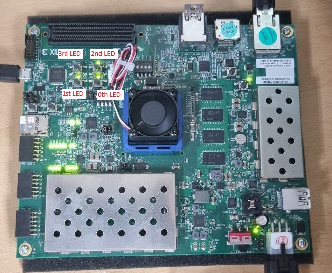
led_out_0, led_out_1, led_out_2, led_out_3: Output wire ports for connecting to LEDs.
- The 0th LED is turned on when the PS sends a signal to the PS.
- The 1st LED is a blinker indicating that an interrupt is triggered from PL to PS.
- The 2nd and 3rd LEDs are connected to the first 2 bits of the 8 KB BRAM.
- The interrupt handler will be triggered by each blink of the 1st LED, and you can see the output by using a serial monitor.
Here's the picture of ZCU104's LEDs placement order.
To utilize this Verilog project, follow these steps:
- Ensure you have Xilinx Vivado installed on your system.
- Clone the source code + TCL script (
hwdbg-zcu104.tcl). - Open
Vivado Tcl Shelland navigate to the directory where you have saved the TCL script (Using thecdcommand). - Run the TCL script by typing
source hwdbg-zcu104.tclin the Vivado command tool. - Vivado will then create a Vivado project for the design.
- Open the generated Vivado project and perform synthesis, implementation, and bitstream generation as per your requirements.
- Once the bitstream is generated, export the hardware to Vivado.
- Open the Vitis IDE.
- Create a platform and an application in Vitis.
- Copy the contents of the
swfolder from the generated Vivado project to the Vitis application project. - Compile the application in Vitis.
- Program the FPGA with the generated bitstream using Vitis.
- Test the functionality of the shared channel over PS <> PL. The LEDs on the ZCU104 board should be changed based on the values produced in the C code.


