Git Product home page Git Product logo

esp8266_milight_hub's Introduction

esp8266_milight_hub Build Status License

This is a replacement for a Milight/LimitlessLED remote/gateway hosted on an ESP8266. Leverages Henryk Plötz's awesome reverse-engineering work.

Milight bulbs are cheap smart bulbs that are controllable with an undocumented 2.4 GHz protocol. In order to control them, you either need a remote ($13), which allows you to control them directly, or a WiFi gateway ($30), which allows you to control them with a mobile app or a UDP protocol.

This project is a replacement for the wifi gateway.

This guide on my blog details setting one of these up.

Why this is useful

  1. Both the remote and the WiFi gateway are limited to four groups. This means if you want to control more than four groups of bulbs, you need another remote or another gateway. This project allows you to control 262,144 groups (4*2^16, the limit imposed by the protocol).
  2. This project exposes a nice REST API to control your bulbs.
  3. You can secure the ESP8266 with a username/password, which is more than you can say for the Milight gateway! (The 2.4 GHz protocol is still totally insecure, so this doesn't accomplish much :).
  4. Official hubs connect to remote servers to enable WAN access, and this behavior is not disableable.
  5. This project is capable of passively listening for Milight packets sent from other devices (like remotes). It can publish data from intercepted packets to MQTT. This could, for example, allow the use of Milight remotes while keeping your home automation platform's state in sync. See the MQTT section for more detail.

Supported remotes

The following remotes can be emulated:

Support has been added for the following bulb types:

Model # Name Compatible Bulbs
FUT096 RGB/W
  1. FUT014
  2. FUT016
  3. FUT103
FUT005
FUT006
FUT007
CCT
  1. FUT011
  2. FUT017
  3. FUT019
FUT098 RGB Most RGB LED Strip Controlers
FUT020 RGB Some other RGB LED strip controllers
FUT092 RGB/CCT
  1. FUT012
  2. FUT013
  3. FUT014
  4. FUT015
  5. FUT103
  6. FUT104
  7. FUT105
  8. Many RGB/CCT LED Strip Controllers
FUT091 CCT v2 Most newer dual white bulbs and controllers
FUT089 8-zone RGB/CCT Most newer rgb + dual white bulbs and controllers

Other remotes or bulbs, but have not been tested.

What you'll need

  1. An ESP8266. I used a NodeMCU.
  2. A NRF24L01+ module (~$3 on ebay). Alternatively, you can use a LT8900.
  3. Some way to connect the two (7 female/female dupont cables is probably easiest).

Installing

Connect the NRF24L01+ / LT8900

This project is compatible with both NRF24L01 and LT8900 radios. LT8900 is the same model used in the official MiLight devices. NRF24s are a very common 2.4 GHz radio device, but require software emulation of the LT8900's packet structure. As such, the LT8900 is more performant.

Both modules are SPI devices and should be connected to the standard SPI pins on the ESP8266.

NRF24L01+

This guide details how to connect an NRF24 to an ESP8266. By default GPIO 4 for CE and GPIO 15 for CSN are used, but these can be configured late in the Web GUI under Settings -> Setup.

NodeMCU Radio Color
GND GND Black
3V3 VCC Red
D2 (GPIO4) CE Orange
D8 (GPIO15) CSN/CS Yellow
D5 (GPIO14) SCK Green
D7 (GPIO13) MOSI Blue
D6 (GPIO12) MISO Violet

Image source: MySensors.org

LT8900

Connect SPI pins (CE, SCK, MOSI, MISO) to appropriate SPI pins on the ESP8266. With default settings, connect RST to GPIO 0, PKT to GPIO 16, CE to GPIO 4, and CSN to GPIO 15. Make sure to properly configure these if using non-default pinouts.

Setting up the ESP

The goal here is to flash your ESP with the firmware. It's really easy to do this with PlatformIO:

export ESP_BOARD=nodemcuv2
platformio run -e $ESP_BOARD --target upload

Of course make sure to substitute nodemcuv2 with the board that you're using.

You can find pre-compiled firmware images on the releases.

Configure WiFi

This project uses WiFiManager to avoid the need to hardcode AP credentials in the firmware.

When the ESP powers on, you should be able to see a network named "ESPXXXXX", with XXXXX being an identifier for your ESP. Connect to this AP and a window should pop up prompting you to enter WiFi credentials. If your board has a built-in LED (or you wire up an LED), it will flash to indicate the status.

The network password is "milightHub".

Get IP Address

Both mDNS and SSDP are supported.

  • OS X - you should be able to navigate to http://milight-hub.local.
  • Windows - you should see a device called "ESP8266 MiLight Gateway" show up in your network explorer.
  • Linux users can install avahi (sudo apt-get install avahi-daemon on Ubuntu), and should then be able to navigate to http://milight-hub.local.

Use it!

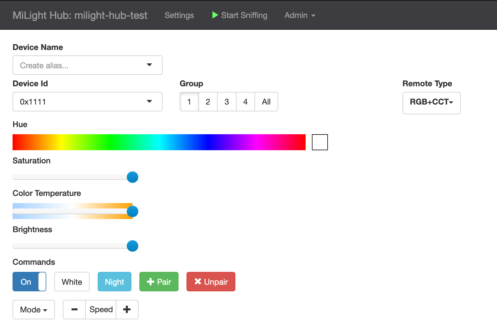
The HTTP endpoints (shown below) will be fully functional at this point. You should also be able to navigate to http://<ip_of_esp>, or http://milight-hub.local if your client supports mDNS. The UI should look like this:

Web UI

If it does not work as expected see Troubleshooting.

Pair Bulbs

If you need to pair some bulbs, how to do this is described in the wiki.

Device Aliases

You can configure aliases or labels for a given (Device Type, Device ID, Group ID) tuple. For example, you might want to call the RGB+CCT remote with the ID 0x1111 and the Group ID 1 to be called living_room. Aliases are useful in a couple of different ways:

  • In the UI: the aliases dropdown shows all previously set aliases. When one is selected, the corresponding Device ID, Device Type, and Group ID are selected. This allows you to not need to memorize the ID parameters for each lighting device if you're controlling them through the UI.
  • In the REST API: standard CRUD verbs (GET, PUT, and DELETE) allow you to interact with aliases via the /gateways/:device_alias route.
  • MQTT: you can configure topics to listen for commands and publish updates/state using aliases rather than IDs.

REST API

Generated API documentation is available here:

API documentation is generated from the OpenAPI spec using redoc.

MQTT

To configure your ESP to integrate with MQTT, fill out the following settings:

  1. mqtt_server- IP or hostname should work. Specify a port with standard syntax (e.g., "mymqttbroker.com:1884").
  2. mqtt_topic_pattern - you can control arbitrary configurations of device ID, device type, and group ID with this. A good default choice is something like milight/:device_id/:device_type/:group_id. More detail is provided below.
  3. (optionally) mqtt_username
  4. (optionally) mqtt_password

More detail on mqtt_topic_pattern

mqtt_topic_pattern leverages single-level wildcards (documented here). For example, specifying milight/:device_id/:device_type/:group_id will cause the ESP to subscribe to the topic milight/+/+/+. It will then interpret the second, third, and fourth tokens in topics it receives messages on as :device_id, :device_type, and :group_id, respectively. The following tokens are available:

  1. :device_id - Device ID. Can be hexadecimal (e.g. 0x1234) or decimal (e.g. 4660).
  2. :device_type - Remote type. rgbw, fut089, etc.
  3. :group_id - Group. 0-4 for most remotes. The "All" group is group 0.
  4. :device_alias - Alias for the given device. Note that if an alias is not configured, a default token __unnamed_group will be substituted instead.

Messages should be JSON objects using exactly the same schema that the REST gateway uses for the /gateways/:device_id/:device_type/:group_id endpoint.

Example:

If mqtt_topic_pattern is set to milight/:device_id/:device_type/:group_id, you could send the following message to it (the below example uses a ruby MQTT client):

irb(main):001:0> require 'mqtt'
irb(main):002:0> client = MQTT::Client.new('10.133.8.11',1883)
irb(main):003:0> client.connect
irb(main):004:0> client.publish('milight/0x118D/rgb_cct/1', '{"status":"ON","color":{"r":255,"g":200,"b":255},"brightness":100}')

This will instruct the ESP to send messages to RGB+CCT bulbs with device ID 0x118D in group 1 to turn on, set color to RGB(255,200,255), and brightness to 100.

Updates

ESPMH is capable of providing two types of updates:

  1. Delta: as packets are received, they are translated into the corresponding command (e.g., "set brightness to 50"). The translated command is sent as an update.
  2. State: When an update is received, the corresponding command is applied to known group state, and the whole state for the group is transmitted.
Delta updates

To publish data from intercepted packets to an MQTT topic, configure MQTT server settings, and set the mqtt_update_topic_pattern to something of your choice. As with mqtt_topic_pattern, the tokens :device_id, :device_type, and :group_id will be substituted with the values from the relevant packet. :device_id will always be substituted with the hexadecimal value of the ID. You can also use :hex_device_id, or :dec_device_id if you prefer decimal.

The published message is a JSON blob containing the state that was changed.

As an example, if mqtt_update_topic_pattern is set to milight/updates/:hex_device_id/:device_type/:group_id, and the group 1 on button of a Milight remote is pressed, the following update will be dispatched:

irb(main):005:0> client.subscribe('milight/updates/+/+/+')
=> 27
irb(main):006:0> puts client.get.inspect
["lights/updates/0x1C8E/rgb_cct/1", "{\"status\":\"on\"}"]
Full state updates

For this mode, mqtt_state_topic_pattern should be set to something like milight/states/:hex_device_id/:device_type/:group_id. As an example:

irb(main):005:0> client.subscribe('milight/states/+/+/+')
=> 27
irb(main):006:0> puts client.get.inspect
["lights/states/0x1C8E/rgb_cct/1", "{\"state\":\"ON\",\"brightness\":255,\"color_temp\":370,\"bulb_mode\":\"white\"}"]
irb(main):007:0> puts client.get.inspect
["lights/states/0x1C8E/rgb_cct/1", "{\"state\":\"ON\",\"brightness\":100,\"color_temp\":370,\"bulb_mode\":\"white\"}"]

Make sure that mqtt_topic_pattern, mqtt_state_topic_pattern, and matt_update_topic_pattern are all different! If they are they same you can put your ESP in a loop where its own updates trigger an infinite command loop.

Customize fields

You can select which fields should be included in state updates by configuring the group_state_fields parameter. Available fields should be mostly self explanatory, but are all documented in the REST API spec under GroupStateField.

Client Status

To receive updates when the MQTT client connects or disconnects from the broker, confugre the mqtt_client_status_topic parameter. A message of the following form will be published:

{"status":"disconnected_unclean","firmware":"milight-hub","version":"1.9.0-rc3","ip_address":"192.168.1.111","reset_reason":"External System"}

If you wish to have the simple messages connected and disconnected instead of the above environmental data, configure simple_mqtt_client_status to true (or set Client Status Message Mode to "Simple" in the Web UI).

UDP Gateways

You can add an arbitrary number of UDP gateways through the REST API or through the web UI. Each gateway server listens on a port and responds to the standard set of commands supported by the Milight protocol. This should allow you to use one of these with standard Milight integrations (SmartThings, Home Assistant, OpenHAB, etc.).

You can select between versions 5 and 6 of the UDP protocol (documented here). Version 6 has support for the newer RGB+CCT bulbs and also includes response packets, which can theoretically improve reliability. Version 5 has much smaller packets and is probably lower latency.

Transitions

Transitions between two given states are supported. Depending on how transition commands are being issued, the duration and smoothness of the transition are both configurable. There are a few ways to use transitions:

RESTful /transitions routes

These routes are fully documented in the REST API documentation.

transition field when issuing commands

When you issue a command to a bulb either via REST or MQTT, you can include a transition field. The value of this field specifies the duration of the transition, in seconds (non-integer values are supported).

For example, the command:

{"brightness":255,"transition":60}

will transition from whatever the current brightness is to brightness=255 over 60 seconds.

Notes on transitions

  • espMH's transitions should work seamlessly with HomeAssistant's transition functionality.
  • You can issue commands specifying transitions between many fields at once. For example:
    {"brightness":255,"kelvin":0,"transition":10.5}
    will transition from current values for brightness and kelvin to the specified values -- 255 and 0 respectively -- over 10.5 seconds.
  • Color transitions are supported. Under the hood, this is treated as a transition between current values for r, g, and b to the r, g, b values for the specified color. Because milight uses hue-sat colors, this might not behave exactly as you'd expect for all colors.
  • You can transition to a given status or state. For example,
    {"status":"ON","transition":10}
    will turn the bulb on, immediately set the brightness to 0, and then transition to brightness=255 over 10 seconds. If you specify a brightness value, the transition will stop there instead of 255.

LED Status

Some ESP boards have a built-in LED, on pin #2. This LED will flash to indicate the current status of the hub:

  • Wifi not configured: Fast flash (on/off once per second). See Configure Wifi to configure the hub.
  • Wifi connected and ready: Occasional blips of light (a flicker of light every 1.5 seconds).
  • Packets sending/receiving: Rapid blips of light for brief periods (three rapid flashes).
  • Wifi failed to configure: Solid light.

In the setup UI, you can turn on "enable_solid_led" to change the LED behavior to:

  • Wifi connected and ready: Solid LED light
  • Wifi failed to configure: Light off

Note that you must restart the hub to affect the change in "enable_solid_led".

You can configure the LED pin from the web console. Note that pin means the GPIO number, not the D number ... for example, D1 is actually GPIO5 and therefore its pin 5. If you specify the pin as a negative number, it will invert the LED signal (the built-in LED on pin 2 (D4) is inverted, so the default is -2).

If you want to wire up your own LED you can connect it to D1/GPIO5. Put a wire from D1 to one side of a 220 ohm resistor. On the other side, connect it to the positive side (the longer wire) of a 3.3V LED. Then connect the negative side of the LED (the shorter wire) to ground. If you use a different voltage LED, or a high current LED, you will need to add a driver circuit.

Another option is to use an external LED parallel to the (inverted) internal one, this way it will mirror the internal LED without configuring a new LED pin in the UI. To do this connect the (short) GND pin of your LED to D4. The longer one to a 220 ohm resistor and finally the other side of the resistor to a 3V3 pin.

Development

This project is developed and built using PlatformIO.

Running tests

On-board unit tests are available using PlatformIO. Run unit tests with this command:

pio test -e d1_mini

substituting d1_mini for the environment of your choice.

Running integration tests

A remote integration test suite built using rspec is available under ./test/remote.

Ready-Made Hub

h4nc (h4nc.zigbee(a)gmail.com) created a PCB and 3D-printable case for espMH. He's offering ready-made versions. Please get in touch with him at the aforementioned email address for further information.

Find more information from the espmh_pcb repository.

Acknowledgements

  • @WoodsterDK added support for LT8900 radios.
  • @cmidgley contributed many substantial features to the 1.7 release.

Donating

If the project brings you happiness or utility, it's more than enough for me to hear those words.

If you're feeling especially generous, and are open to a charitable donation, that'd make me very happy. Here are some whose mission I support (in no particular order):

esp8266_milight_hub's People

Contributors

amelchio avatar aneisch avatar annego15 avatar bartrumb avatar bauerj avatar bombcheck avatar cmidgley avatar erriez avatar gei0r avatar h4nc avatar hastarin avatar jmw6773 avatar juupje avatar jvanderzande avatar markharleman avatar michaeldancurtis avatar mlewand avatar munkeyballs avatar nordeep avatar pinkeen avatar rjsachse avatar sidoh avatar slootjes avatar starkillerog avatar

Stargazers

 avatar  avatar  avatar  avatar  avatar  avatar  avatar  avatar  avatar  avatar  avatar  avatar  avatar  avatar  avatar  avatar  avatar  avatar  avatar  avatar  avatar  avatar  avatar  avatar  avatar  avatar  avatar  avatar  avatar  avatar  avatar  avatar  avatar  avatar  avatar  avatar  avatar  avatar  avatar  avatar  avatar  avatar  avatar  avatar  avatar  avatar  avatar  avatar  avatar  avatar  avatar  avatar  avatar  avatar  avatar  avatar  avatar  avatar  avatar  avatar  avatar  avatar  avatar  avatar  avatar  avatar  avatar  avatar  avatar  avatar  avatar  avatar  avatar  avatar  avatar  avatar  avatar  avatar  avatar  avatar  avatar  avatar  avatar  avatar  avatar  avatar  avatar  avatar  avatar  avatar  avatar  avatar  avatar  avatar  avatar  avatar  avatar  avatar  avatar  avatar

Watchers

 avatar  avatar  avatar  avatar  avatar  avatar  avatar  avatar  avatar  avatar  avatar  avatar  avatar  avatar  avatar  avatar  avatar  avatar  avatar  avatar  avatar  avatar  avatar  avatar  avatar  avatar  avatar  avatar  avatar  avatar  avatar  avatar  avatar  avatar  avatar  avatar  avatar  avatar  avatar  avatar  avatar  avatar  avatar  avatar  avatar  avatar  avatar  avatar  avatar  avatar  avatar  avatar  avatar  avatar  avatar  avatar  avatar  avatar  avatar  avatar  avatar  avatar  avatar  avatar  avatar  avatar  avatar  avatar  avatar  avatar  avatar  avatar  avatar

esp8266_milight_hub's Issues

Is it possible implement new OEM (partially Milight) protocol?

I recieve yesterday some RGBW OEM China LED plate - https://detail.1688.com/offer/522143371857.html?spm=a2615.2177701.0.0.hO79R9
When i sniff it, i see this syncword 0x050A 0x55AA and channels 0x04 (4) and 0x4A( 74), command with 7 byte payload, like 0xC2 0xDC 0xA0 0xAB 0x01 0xBE 0x00 (Power On All), 0xC2 0xDC 0xA0 0xAB 0x02 0xC1 0x00 (power Off ALL).
I believe that this is very similar to the description of the old MiLigh protocol - http://arduino-projects4u.com/milight-rf-control/
Can you help me for it's implemention?

Fade In / Out mode

I suggest you a simple mod for bulbs.

When you turn off bulbs that are in maximum brightness, and then you want to re-light them, but at low light, they light up at full brightness and only then reduce their power.
This can be unpleasant when you are in the dark and you want to light the lights dimly.

It would seem that this is the nominal operation of the original Milight bridge: it is necessary to light the bulbs before adjusting their brightness.

Would it be possible to implement an optional function capable of systematically putting the lamps at minimum power before extinguishing them? As a result, the lamps will illuminate at low power before having the desired brightness.

What do you think ?

Support HomeAssistant JSON schema

Schema is outlined here.

Schema is mostly one-to-one with what exists, but has some minor differences.

  • state instead of status, and values are capitalized.
  • brightness instead of level, and scale is [0,255] instead of [0,100].
  • color with r, g, b keys instead of hue and saturation. Also supports Hue's XY color scheme. Will need an RGB->HSV converter.
  • white_value instead of temperature using the mired scale. Will need to figure out how to map this to [0,100].

This will allow for a nicer, easier integration with HomeAssistant because:

  • Using UDP servers means standing up unauthenticated services on the network, and requires the user to stand up one UDP server per device ID.
  • Using the REST API would solve this, but there's no direct integration.
  • Using MQTT will be much easier if it's just a matter of pointing at a topic and selecting the mqtt_json platform.

Pipeline Issues with python-limitlessled

An issue exists where pipelines are used, brightness/color change does not function as expected. Instructions seem to be dropped when concurrent operations are called. This issue exists when triggering scenes from Home Assistant.

Milight app on Google play

Is Milight app (ver2 or ver3) in Google Play should see udp server and if yes, on wich port?
24-03-2017 115146
If i lauch MiApp ver2 and use udp port 48899 - on serial console i see:
*WM: IP Address:
*WM: 192.168.137.215
Error, unexpected packet length (should always be 2-3, was: 5
Error, unexpected packet length (should always be 2-3, was: 10
Error, unexpected packet length (should always be 2-3, was: 5
Error, unexpected packet length (should always be 2-3, was: 10
Error, unexpected packet length (should always be 2-3, was: 5
Error, unexpected packet length (should always be 2-3, was: 10

No WiFi connection after upgrade via web interface

After initial flashing with v1.2.1 via platformio and configuration via wifimanager the web interface is available and looking great!
I checked for update and updated to 1.2.2 after which time the device never re-connected to the network.
Re-flashing with 1.2.1 or 1.2.1 (via build and git tags in platformio) has not made the device visible on the network again.

Obviously fixing the issues is the goal, but did beg some questions:
How can I reset the WiFi manager if the device has not connected to the network
Is there a serial connection available, and if so what commands etc. are available. What settings/command would be used to initiate this connection.

Add support for v2 CCT bulbs

Raised by @lstt2005 in #14. The protocol has some minor differences from the one used by the RGB+CCT remotes:

  1. b[1] is 0x21 instead of 0x20. I'm assuming that b[1] indicates remote type or something like that.
  2. The command 0x02 is brightness. (It's color for the remote types I have).
  3. The argument for brightness is scrambled using different additive offsets. Would need to scrape some packets to reverse these.

Commands for on, off, and color temperature appear to use the same codes and RF configs.

Will need to:

  1. Add a way to specify b[1].
  2. Reverse additive offsets for brightness command.
  3. Add a new remote type in the UI / RF configs.

Improve listen reliability

Listening for packets does not work reliably.

It seems that it never works to switch between radio configs (RGBW, CCT, etc.) without restarting either the nrf or the esp.

Potentially setting changes to the nrf are not sticking when it's already been initialized.

Some question about UDP v6 and support MiLight 3.0

As i write earlier, i found github Android project Bilight - https://github.com/JasperG/bilight
When i experiment with it, sometimes, i see this messages in ESP8266 console:
"
Received request with untracked session ID: 0
"
Sometimes be, sometimes no. Question - is it application problem or some bug in ESP8266 library?
30-03-2017 112500

LT8900 stability regression?

I try work with LT8920, it's work very stable with old branch - esp8266_milight_hub-mqtt from 20.04.2017.
But when i try work with master branch from now time - LT8920 work VERY UNSTABLE with different settings RF packets etc...((( I try REFLASH old library and master - 3 times, include SPIFFS...

Clean up REST endpoint token parsing

Right now the code that handles parsing for endpoints with tokens (e.g., /a/:b/:c) is very POCy. It's using a shitty copy/paste Vector impl and is putting a ton of stuff on the heap.

Allow webapp to run on Apache etc. with USB NRF24L01+

Allow webapp to run on Apache etc. with USB NRF24L01+, such that any network connected device with USB could potentially become a gateway (rPi or other persistent server device on the network). Also reduces the WiFi device count 8)

HTTP request in order to set specific disco mode

Hi Chris,

I suggest you an enhancement :-)

On the RGBW protocol, the first byte is the type of Disco mode (from 0xB0 to 0xB8)
Is it possible to implement a function in order to set a specific mode instead of classic mode (increment) ?

Moreover Is it possible to implement this mode for CCT bulbs ?

Best regards,
Jerome

Support POSTing to endpoints that accept PUT commands

I have written an integration for this project that works with this project over here: https://github.com/fireboy1919/MiThings

And it works! Works great, actually. Unfortunately, though, Smartthings hub is super buggy, and I had to modify one thing.

Specifically, Smartthings doesn't support PUT requests. I don't know why. Same exact command as post, but with a different verb, and it doesn't go out. I have a bug request in and will be ready if they ever decide to fix it.

In the meantime, I added an extra line to my compiled version of this project to support POST requests for sending bulb commands. Seems to work fine.

How would you feel about adding or changing that command to a POST rather than a PUT?

Multiple issues on CCT bulbs

Hi Chris,

Another feedback !
I just tested CCT bulbs and I have multiple issues with the V5 UDP Gateway:

Malformed packets on Brightness Up and Down commands:

Sending packet: 5A**FFFFFF**04CFCF
                              Elapsed: 128
Sending packet: 5A**FFFFFF**04D0D0
                              Elapsed: 116
Sending packet: 5AFFFFFF04D1D1
                              Elapsed: 129
Sending packet: 5AFFFFFF04D2D2
                              Elapsed: 121
Sending packet: 5AFFFFFF04D3D3
                              Elapsed: 125
Sending packet: 5AFFFFFF04D4D4
                              Elapsed: 117
Sending packet: 5AFFFFFF04D5D5
                              Elapsed: 115

And same thing for Color Temperature packets:

Sending packet: 5A**FFFFFF**0EDEDE
                              Elapsed: 132
Sending packet: 5A**FFFFFF**0EDFDF
                              Elapsed: 117
Sending packet: 5AFFFFFF0EE0E0
                              Elapsed: 112
Sending packet: 5AFFFFFF0EE1E1
                              Elapsed: 135
Sending packet: 5AFFFFFF0FE2E2
                              Elapsed: 114
Sending packet: 5AFFFFFF0FE3E3
                              Elapsed: 124
Sending packet: 5AFFFFFF0FE4E4
                              Elapsed: 115

Brightness and Color Temperatures are OK with the WebUI.

All On and All Off commands not recognized from UDP Gateway:

V5MiLightUdpServer - Unhandled command: 53
V5MiLightUdpServer - Unhandled command: 57

Attempted commands are:
35 00 55 - All On
39 00 55 - All Off

Same thing from the WebUI: malformed packets. (Groups 1 From 4 are OK.)

Sending packet: 5AD24E**0000**F0F0
                              Elapsed: 120
Sending packet: 5AD24E**0000**F1F1
                              Elapsed: 120
Sending packet: 5AD24E0000F2F2
                              Elapsed: 121
Sending packet: 5AD24E0000F3F3
                              Elapsed: 104

Expected Packets are:
ON ==> 5AD24E0009xyxy
OFF ==> 5AD24E0005xyxy

Best regards,
Jerome

Discovery MAC address

Hey,
I just finished building a DIY milight hub. Unfortunately when I try to pair it with the V6 protocoll and Openhab the discovery package gets the following return:

18 00 00 00 40 02 00 00 00 00 C7 6A 00 20 39 38 35 62 31 35 37 62 66 36 66 63 34 33 33 36 38 61 36 33 34 36 37 65 61 33 62 31 39 64 30 64 01 00 01 17 63 00 00 05 00 09 78 6C 69 6E 6B 5F 64 65 76 07 5B CD 15

Is it something like an encoded address?

I tracked it down to this part of the code:

uint8_t V6MiLightUdpServer::SEARCH_RESPONSE[] = {
  0x18, 0x00, 0x00, 0x00, 0x40, 0x02,
  0xFF, 0xFF, 0xFF, 0xFF, 0xFF, 0xFF, // mac address
  0x00, 0x20, 0x39, 0x38, 0x35, 0x62,
  0x31, 0x35, 0x37, 0x62, 0x66, 0x36,
  0x66, 0x63, 0x34, 0x33, 0x33, 0x36,
  0x38, 0x61, 0x36, 0x33, 0x34, 0x36,
  0x37, 0x65, 0x61, 0x33, 0x62, 0x31,
  0x39, 0x64, 0x30, 0x64, 0x01, 0x00,
  0x01,
  0x17, 0x63,  // this is 5987 in hex. specifying a different value seems to
               // cause client to connect on a different port for some commands
  0x00, 0x00, 0x05, 0x00, 0x09, 0x78,
  0x6C, 0x69, 0x6E, 0x6B, 0x5F, 0x64,
  0x65, 0x76, 0x07, 0x5B, 0xCD, 0x15
};

The OpenHab implementation doesn't allow the usage of a device without the right mac address in a config. Sadly I don't really get this code. Is it a hardcoded MAC address or is just something buggy? I would appreciate your help!

Thanks.

Support Philips Hue API

It occurred to me that while it is nice to emulate the UDP protocol supported by Milight, it might even better to emulate the protocol supported by something else - noteably, Phillips Hue or LiFX.

Obviously, that would require storing group state information on the Controller, but it would make the project much, much easier to integrate with other systems.

The other nice thing is that at least some of the work is already done, and only needs porting -
Controlling a bridge from a shield in Arduino code:
https://gist.github.com/jamesabruce/8bc9faf3c06e30c3f6fc

Emulating everything:
https://github.com/bwssytems/ha-bridge

Obviously, this might be a big undertaking. But it might be worth it.

Multiple gateways in MiLIght app V3 ?

Can any chance make support (may be in library?) for support multiple gateways in MiLIght app V3 (in tabs of gateways) works with one ESP - maybe on other UPD ports? Very cool and comfortable application for bulbs and LED strips..

Support official UDP discovery

From the Limitless LED page, you can discover a hub in the milight app like this:

  • Step 1:Send UDP message to the LAN broadcast IP address of "10.10.100.255" and port of 48899 => "Link_Wi-Fi"

  • All Wifi bridges on the LAN will respond with their details. Response is "10.10.100.254, ACCF232483E8"

  • Step 2 (optional for changing settings on the wifi bridge): Then send "+ok" to the LimitlessLED Wifi Bridge. Send UDP message to the response IP address returned from step 1 "10.10.100.254" => "+ok"

  • Step 3 (optional for changing settings on the wifi bridge): After that you may send AT commands (ending with \r\n) to the module.


Obviously, there's no way to get the app to figure out how to work on ports other than the default, but essentially with this one addition, the esp8266 milight hub would be a superior drop-in replacement for the original hub.

Add support for "Disco" modes for HTTP & Web UI.

As far as I can see (Looking through the code), the Disco modes are only supported via the official UDP implementation, and possibly only as cycling through them, by simulating a button push.

Sniffer mode not working on RGBW mode

Hi Chris,

It has a bug on the sniffer module.

After a cold start, when I start sniffing on rgbw mode, it does not receive any packet...
I need to start sniffing to another mode (CCT for example) and switch back to RGBW.

Tested with nRF24L01.

Best regards,
Jerome

Support for `4CH WRGB Saturation`

I have a semi experimental remote and controller sold to me by Limitless LED in New Zealand. The controller is still available here and is the 4CH WRGB Saturation type.
The remote is as: this

I have managed to sniff commands only in RGBW mode. The standard RGBW controls from the web interface work, with the quirk that pressing white increases brightness
Below is a mix of the output from the web interface with debug output together with the button pressed. The second line of packet received, packet transformed is from a second run through.
I can confirm that sending the capture packets back produces the correct result.
I am quietly hoping that the R,G,B, and W can be specified as levels ie {"r":255,"g":240,"b":255, "w":255} or saturation + white level

Device ID: 0xAC34
Off
  Packet received (7 bytes):
  Request type  : B0
  Device ID     : AC34
  b1            : 71
  b2            : 04
  b3            : 0B
  Sequence Num. : FD
  Packet received: A4AE01D352C8E80408F6BC9F
  Packet transformed: 07B8AC34710102F1D693
  Packet received: A4AE01D352C682040C84D05F
  Packet transformed: 07B8AC3416040213B2A0
On
  Packet received (7 bytes):
  Request type  : B0
  Device ID     : AC34
  b1            : 71
  b2            : 04
  b3            : 0D
  Sequence Num. : FC
  Packet received: A4AE01D352C8E00804F9F8BF
  Packet transformed: 07B8AC34710001F2F9D1
  Packet received: A4AE01D352C6800802820B9F
  Packet transformed: 07B8AC3416000114049D
W+
  Packet received (7 bytes):
  Request type  : B8
  Device ID     : AC34
  b1            : 71
  b2            : 04
  b3            : 0C
  Sequence Num. : FB
  Packet received: A4AE01D352C8E80C0CF3895F
  Packet transformed: 07B8AC34710103F31CA9
  Packet received: A4AE01D352C6880C0A887A7F
  Packet transformed: 07B8AC3416010315E1E5
W-
  Packet received (7 bytes):
  Request type  : B8
  Device ID     : AC34
  b1            : 71
  b2            : 04
  b3            : 0A
  Sequence Num. : FA
  Packet received: A4AE01D352C8E80202FD509F
  Packet transformed: 07B8AC34710104F4AB90
  Packet received: A4AE01D352C688020684E59F
  Packet transformed: 07B8AC3416010416729A
R+
  Packet received (7 bytes):
  Request type  : B8
  Device ID     : AC34
  b1            : 71
  b2            : 04
  b3            : 09
  Sequence Num. : F9
  Packet received: A4AE01D352C8E40A0AF79EEF
  Packet transformed: 07B8AC34710205F59E77
  Packet received: A4AE01D352C6840A0E8E2BEF
  Packet transformed: 07B8AC3416020517477D
R-
  Packet received (7 bytes):
  Request type  : B8
  Device ID     : AC34
  b1            : 71
  b2            : 03
  b3            : 08
  Sequence Num. : F8
  Packet received: A4AE01D352C8E40606FB6F6F
  Packet transformed: 07B8AC34710206F66D6F
  Packet received: A4AE01D352C684060181BF5F
  Packet transformed: 07B8AC3416020618D8AF
G+
  Packet received (7 bytes):
  Request type  : B8
  Device ID     : AC34
  b1            : 71
  b2            : 03
  b3            : 07
  Sequence Num. : F7
  Packet received: A4AE01D352C8EC0E0EF07BCF
  Packet transformed: 07B8AC34710307F7E03D
  Packet received: A4AE01D352C68C0E098AABFF
  Packet transformed: 07B8AC341603071955FD
G-
  Packet received (7 bytes):
  Request type  : B8
  Device ID     : AC34
  b1            : 71
  b2            : 02
  b3            : 06
  Sequence Num. : F6
  Packet received: A4AE01D352C8EC0101FFB62F
  Packet transformed: 07B8AC34710308F8DF46
  Packet received: A4AE01D352C68C010586032F
  Packet transformed: 07B8AC341603081A064C
B+
  Packet received (7 bytes):
  Request type  : B8
  Device ID     : AC34
  b1            : 71
  b2            : 02
  b3            : 05
  Sequence Num. : F5
  Packet received: A4AE01D352C8E20909FD143F
  Packet transformed: 07B8AC34710409F98BC2
  Packet received: A4AE01D352C682090D84A13F
  Packet transformed: 07B8AC341604091B52C8
B-
  Packet received (7 bytes):
  Request type  : B8
  Device ID     : AC34
  b1            : 71
  b2            : 01
  b3            : 04
  Sequence Num. : F4
  Packet received: A4AE01D352C8E20505F1E5BF
  Packet transformed: 07B8AC3471040AFA78DA
  Packet received: A4AE01D352C68205038A169F
  Packet transformed: 07B8AC3416040A1C8596
S-
  Packet received (7 bytes):
  Request type  : B8
  Device ID     : AC34
  b1            : 71
  b2            : 01
  b3            : 03
  Sequence Num. : F3
  Packet received: A4AE01D352C8E2030DF84F9F
  Packet transformed: 07B8AC3471040CFB219F
  Packet received: A4AE01D352C682030B83BCBF
  Packet transformed: 07B8AC3416040C1DDCD3
M
  Packet received (7 bytes):
  Request type  : B8
  Device ID     : AC34
  b1            : 71
  b2            : 00
  b3            : 01
  Sequence Num. : F2
  Packet received: A4AE00D352C8E20B03F5534F
  Packet transformed: 07B0AC3471040DFCAA2C
  Packet received: A4AE00D352C6820B078CE64F
  Packet transformed: 07B0AC3416040D1E7326
S+
  Packet received (7 bytes):
  Request type  : B8
  Device ID     : AC34
  b1            : 71
  b2            : 01
  b3            : 02
  Sequence Num. : F1
  Packet received: A4AE00D352C8E20D0BFCF96F
  Packet transformed: 07B0AC3471040BFDF369
  Packet received: A4AE00D352C6820D0F854C6F
  Packet transformed: 07B0AC3416040B1F2A63

Please excuse me if this is all in hand and undersood.
There was some discussion here

Replay mode (send regularly last known state to all bulbs)

Hi Chris,

I suggest to you an enhancement:
Milight bulbs are not able to stay off after a power outage and light on when power is recovered.

Is it possible to add a mode that resend regularly the last know state of the bulb ?
The period may be adjusted by a parameter on the webui (in minuts)

Consequently, after a power outage, the bridge will switch off necessary light according to the last known state.
Moreover, we can also add a feature that switch off all lightsfor all UDP bridges at startup.

What do you think about this ?

Regards,
Jerome

Addition for dual white bulbs formatter

What about making a frame that drives the bulbs all the way up in light levels and color all warm.
Then a known state can be achieved, and it will be possible to dim and color set to a known state.

Version with original LT8900(LT8910-8920) module

Chris! Is it possible make version of library with support original LT8910 module support? It's fully describe in https://bitbucket.org/robvanderveer/lt8900lib
21-03-2017 085506
IMHO is easer and simple, that use VIRTUAL NRF24...
I use it to decode all packets.
It's cost in Cina on Taobao - ¥ 3.35 ( 约USD 0.49)
This guys also use this module https://authometion.com/shop/it/
Their forum -http://www.authometion.com/forum/viewforum.php?f=2
Their repo - https://github.com/pmoscetta/authometion-milight

Disco Mode Not working on RGBW bulbs

Hi Chris,

As mentioned on other posts, i'm testing your 1.2.0 version.
The Disco mode does not work as expected comparing to the original bridge.

On the 7 bytes sequence, I think you have forgotten to increment the first byte on 0xB0 => 0xB8 range

(Although Disco mode works properly with RGB+CCT bulbs)

Rgds,
Jerome

UDP server "ALL GROUP ON/OFF" are backwards

If you send the UDP signal for "ALL ON" (42 00 55 - All On) it turns everything off

If you Send the UDP signal for "ALL OFF" (41 00 55 - All Off) it turns everything on

Group UDP functions correctly:

45 00 55 - Zone 1 On
46 00 55 - Zone 1 Off
47 00 55 - Zone 2 On
48 00 55 - Zone 2 Off
49 00 55 - Zone 3 On
4A 00 55 - Zone 3 Off
4B 00 55 - Zone 4 On
4C 00 55 - Zone 4 Off

Version 5

Tested with app first, then with UDP Sender...

Used RGBW Bulbs with Zone 1 and RGBW LED Driver with Zone 2

No further devices tested as I don't have any

A new multi command protocol

The project as it is already supports the existing protocols, and therefor also the different software that uses them, but what about making a high performance WIFI command protocol, that supports multiple actions in one frame.
This will remove some WIFI overhead.

This can be done using different methods:

  • use the same http interface, "daisy chaining" the commands
  • adding mqtt as a transport layer and then "daisy chaining" the commands into a JSON.

Recommend Projects

  • React photo React

    A declarative, efficient, and flexible JavaScript library for building user interfaces.

  • Vue.js photo Vue.js

    🖖 Vue.js is a progressive, incrementally-adoptable JavaScript framework for building UI on the web.

  • Typescript photo Typescript

    TypeScript is a superset of JavaScript that compiles to clean JavaScript output.

  • TensorFlow photo TensorFlow

    An Open Source Machine Learning Framework for Everyone

  • Django photo Django

    The Web framework for perfectionists with deadlines.

  • D3 photo D3

    Bring data to life with SVG, Canvas and HTML. 📊📈🎉

Recommend Topics

  • javascript

    JavaScript (JS) is a lightweight interpreted programming language with first-class functions.

  • web

    Some thing interesting about web. New door for the world.

  • server

    A server is a program made to process requests and deliver data to clients.

  • Machine learning

    Machine learning is a way of modeling and interpreting data that allows a piece of software to respond intelligently.

  • Game

    Some thing interesting about game, make everyone happy.

Recommend Org

  • Facebook photo Facebook

    We are working to build community through open source technology. NB: members must have two-factor auth.

  • Microsoft photo Microsoft

    Open source projects and samples from Microsoft.

  • Google photo Google

    Google ❤️ Open Source for everyone.

  • D3 photo D3

    Data-Driven Documents codes.