Automatic LDR Based Night Lamp.
In order to detect the intensity of light or darkness, we use a sensor called an LDR (light dependent resistor). The LDR is a special type of resistor that allows higher voltages to pass through it (low resistance) whenever there is a high intensity of light, and passes a low voltage (high resistance) whenever it is dark. We can take advantage of this LDR property and use it in our DIY Arduino LDR sensor project.
How Does It Work?
This system works by sensing the intensity of light in its environment. The sensor that can be used to detect light is an LDR. It's inexpensive, and you can buy it from any local electronics store or online.
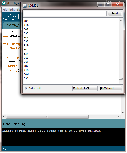
The LDR gives out an analog voltage when connected to VCC (5V), which varies in magnitude in direct proportion to the input light intensity on it. That is, the greater the intensity of light, the greater the corresponding voltage from the LDR will be. Since the LDR gives out an analog voltage, it is connected to the analog input pin on the Arduino. The Arduino, with its built-in ADC (analog-to-digital converter), then converts the analog voltage (from 0-5V) into a digital value in the range of (0-1023). When there is sufficient light in its environment or on its surface, the converted digital values read from the LDR through the Arduino will be in the range of 800-1023.
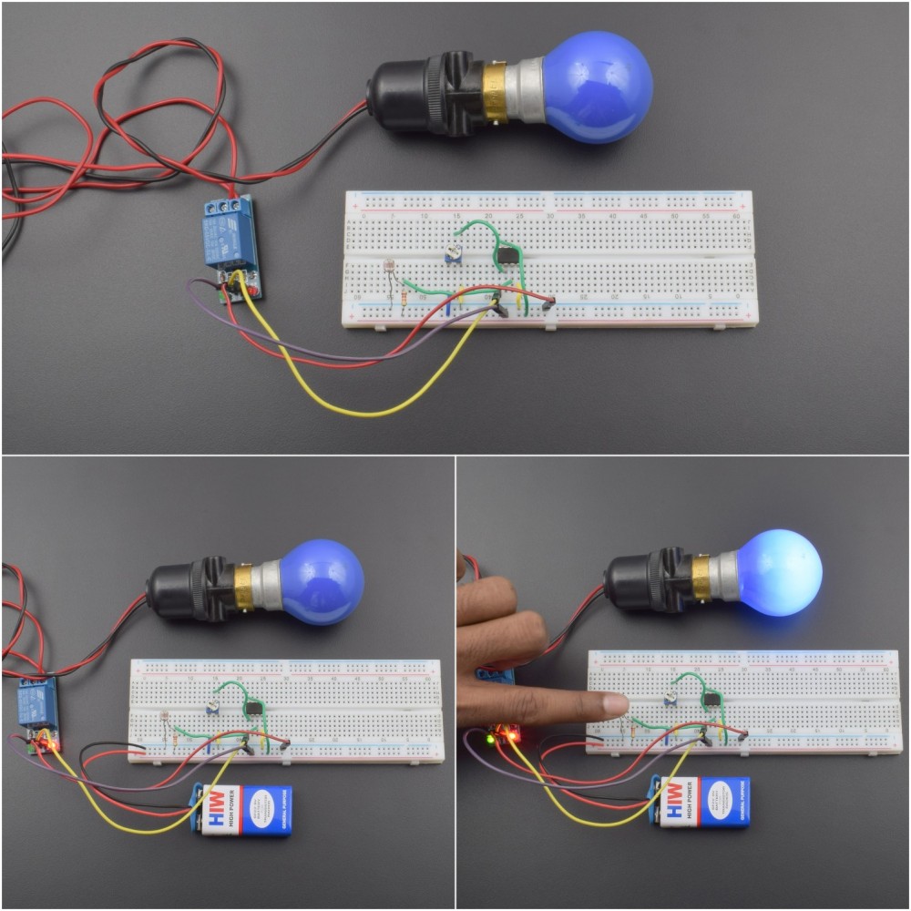
Furthermore, we then program the Arduino to turn on a relay. Correspondingly, turn on an appliance (light bulb), when the light intensity is low (this can be done by covering the surface of the LDR with any object), that is, when the digital values read are in a higher range than usual.
Arduino LDR Sensor Connections
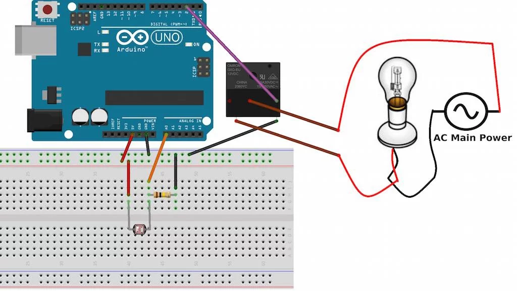
First, you need to connect the LDR to the analog input pin 0 on the Arduino. You have to use a voltage divider configuration to do this. The connection diagram for the Arduino is as given below.
One leg of the LDR is connected to VCC (5V) on the Arduino, and the other to the analog pin 0 on the Arduino. A 100K resistor is also connected to the same leg and grounded.
Connecting the Relay to the Arduino
A relay is an electromechanical switch. It can be used to turn an appliance ON/OFF working on AC/DC. When the Arduino supplies HIGH voltage (5V) to the relay, it turns it on (the switch is ON), otherwise, it remains off.
In this project, we used a 5V SPDT (single pole double throw) relay. One terminal of the relay coil is connected to the Arduino's digital pin 2 and the other end to GND. We connected a light bulb to it as well. Since we are dealing with high power AC voltages, be sure to take proper precautions. If you are still confused about connecting a relay to an appliance, read this article on Relay logic. The overall circuit is shown below.
In this sketch, we set a threshold light value as 700, but it can vary for your projects. You will need to find out the particular value at which the light bulb should turn on. This needs to be done after testing it empirically. So basically, the Arduino turns on the light bulb (via the relay) whenever the light intensity falls below 700. When it is above 700, it turns the light bulb off. Here's a video showing it in action.
