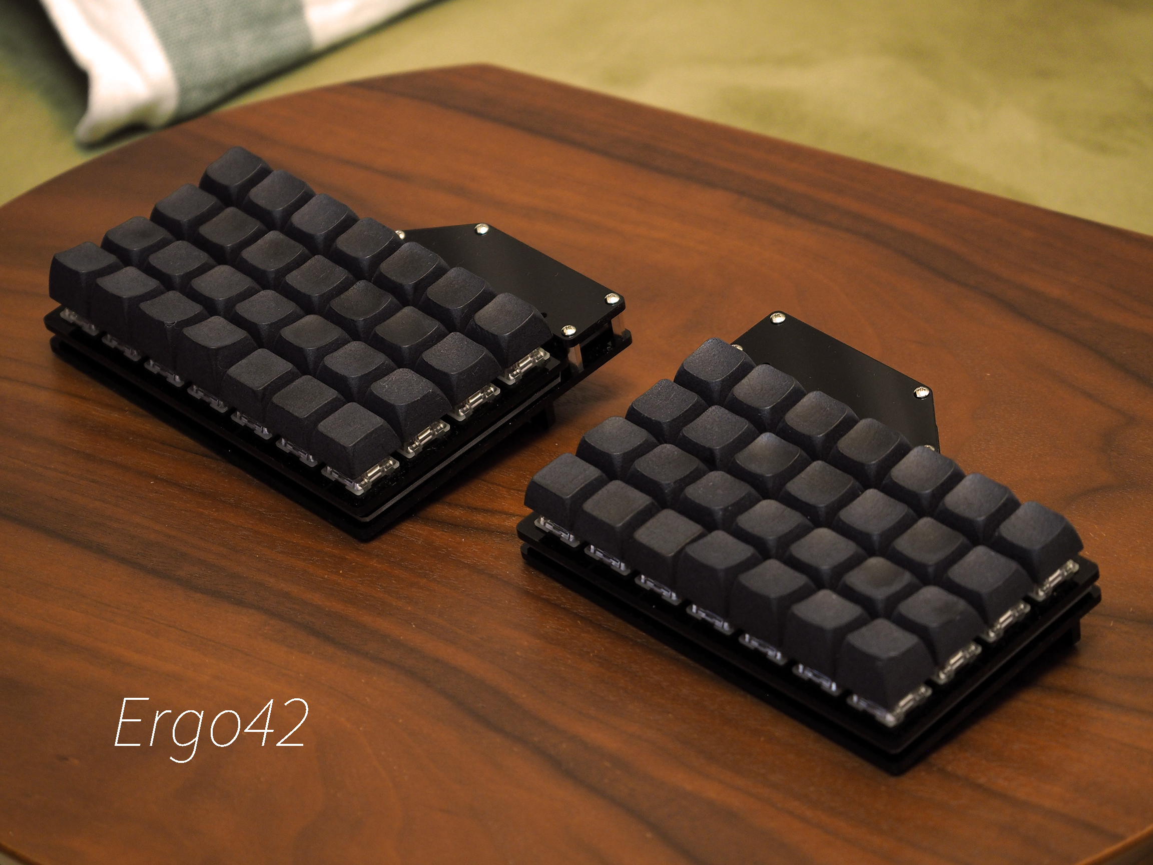
The Answer to the Ultimate Question of Life, the Universe, and at least Keyboards.
7x4 ortho linear split keyboard.
Caution! Ergo42 after version 2.0.0 is not compatible with version 1 seriese design. If you build Ergo42 version 1 seriese, please refer 1.x branch.
- 2 PCB
- 2 5V/16MHz Pro Micro compatible boards
- 56 1N4148 (THD) or 1N4148w (SMD) diodes
- 2 MJ-4PP-9 TRRS jacks
- 2 Case plate set (design available on this repo)
- 10 5 mm (Cherry MX) / 3 mm (Kailh low profile) height M2 standoffs (3 mm height standoffs are under verifing)
- 8 15 mm height M2 standoffs
- 36 6 mm M2 screws
- 2 2 pin tact switch
- 56 Switches of your choice
- 1 TRRS / TRS cable
The screws may have a slight clearance issue with the keycap. Use a screw with a lower profile head.
Place the PCB as TRRS jacks on the inside, closest to one another.
- The left PCB will have the TRRS jack on the right
- The right PCB will have the TRRS jack on the left
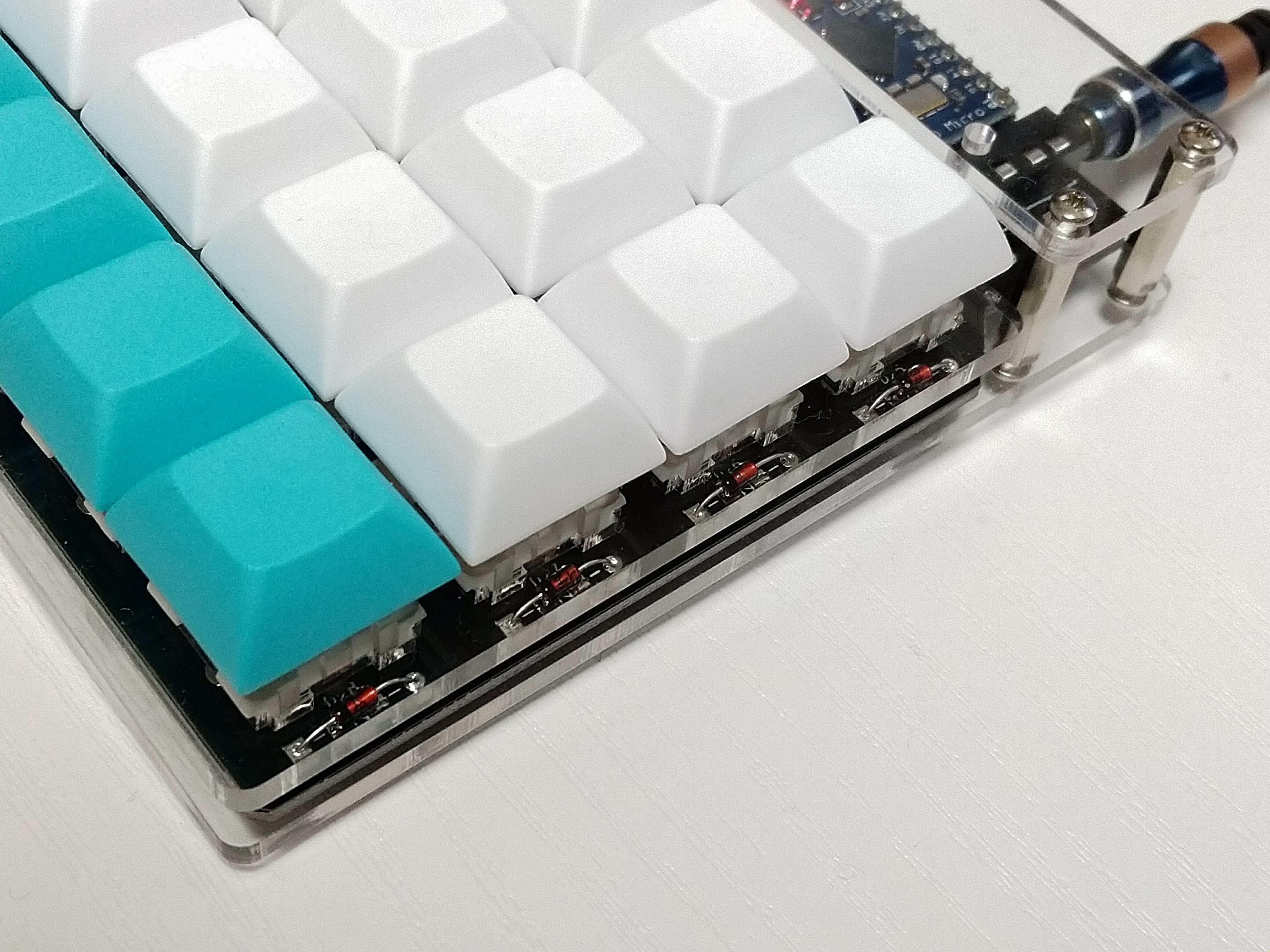
Solder diodes on which side is depending on your switch plate's thickness and key switch type, which is Cherry MX compatible or Kailh low profile. Acrylic plate thickness < 3 mm with Cherry MX compatibles should have diodes on the same side of key switches. Acrylic plate thickness 2 mm with Kailh low profile switches should have diodes on the other side of key switches.
Double check your work. Black lines (THD) / White lines (SMD) should be facing the square pad.
If you want to use I2C, not UART, to comunicate with other side PCB, you should add 2.2 k ohm resistors on left side PCB's R1 and R2 printed silk. And bridge to short W1 pad by solder jumper on each side PCB. Usualy you don't have to do this step.
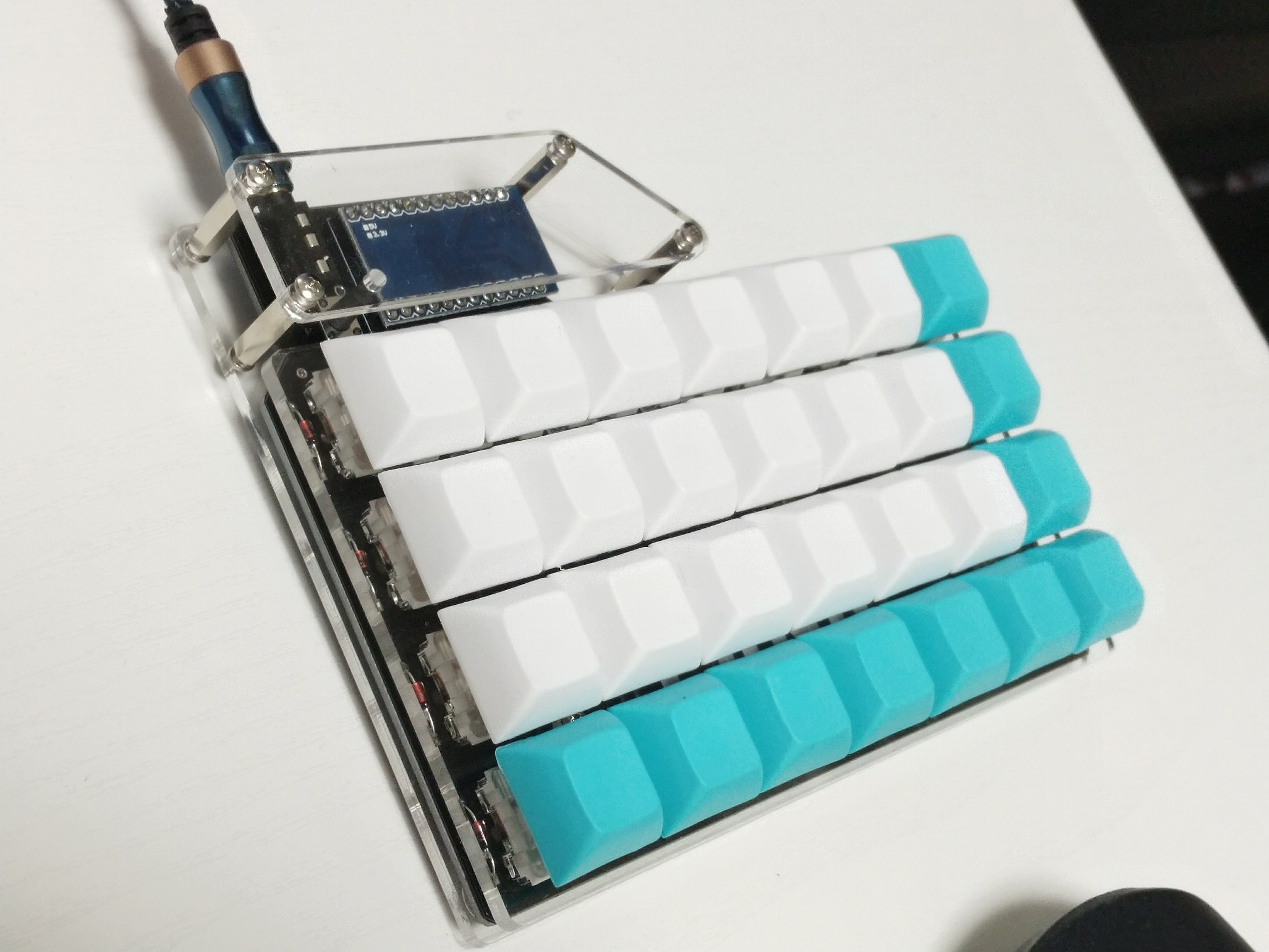
Mount the TRRS jack and tact switch on the same side of your switches. It should be on upper face.
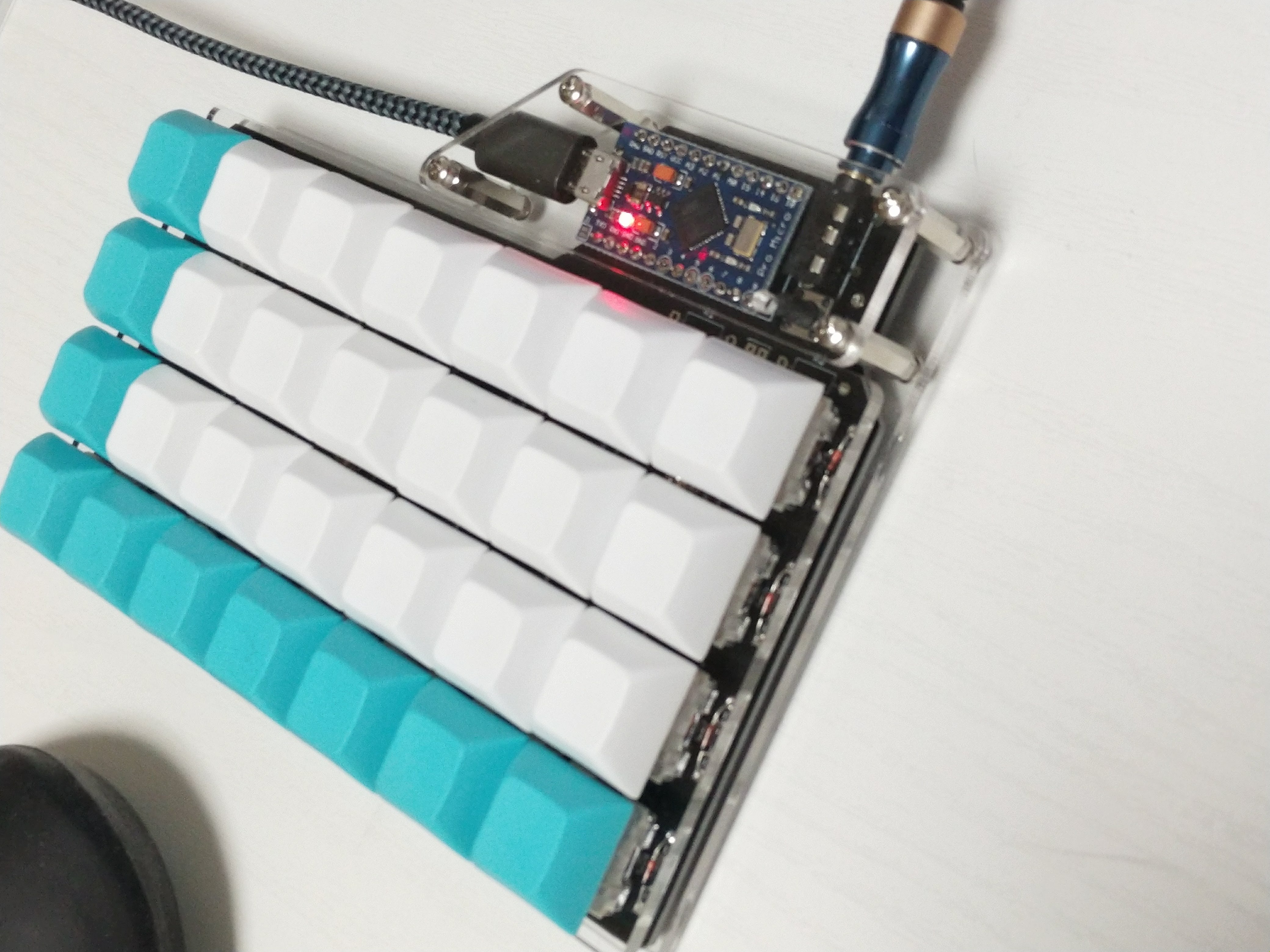
Ergo42's PCB is symmetrical but Pro Micro mount is different between left and right PCB.
- On the left PCB the Pro Micro's component side should be back to PCB.
- On the right PCB the Pro Micro's component side should be face to PCB.
Mount switches on the acrylic plate, set PCB to fit and solder switches. Nothing is difficult.
Tighten the screws with standoffs. Some vinyl pads may help the keyboard's stability. Install your keycaps.
QMK firmware for Ergo42 now abilable on QMK firmware. This document doesn't cover how to build QMK. Prease refer to QMK documents.
Conntect the keyboard by usb cable to PC and run
$ make ergo42/rev1:default:avrdude
on left and right side keyboard each.
It will build and try to flash your firmware. Follow the instractions that require to reset the Pro Micro.
This process may require privileges. If you have some Permission denied error, please try
$ sudo make ergo42/rev1:default:avrdude


