A device designed for controlling the remote garage doors (433Mhz). It can be powered and controlled from 7 to 30 volts, which make it perfect for integrating and using in the cars.
- Wide power supply range: from 7V to 30V;
- The consumption: 9mA during idle, 20mA during transmission;
- The input pin accepts a wide range of voltage: from 3.3V to 30V;
- Overcurrent protection and reverse current protection;
- The device uses one of the most popular RF 433MHz transmitter (cheap and very popular);
- JTAG pins (3x2) used for programming the microcontroller;
- 5V power pins (max current: 50mA), for supplying low current device;
- Transmission and idle indicator (the red LED).

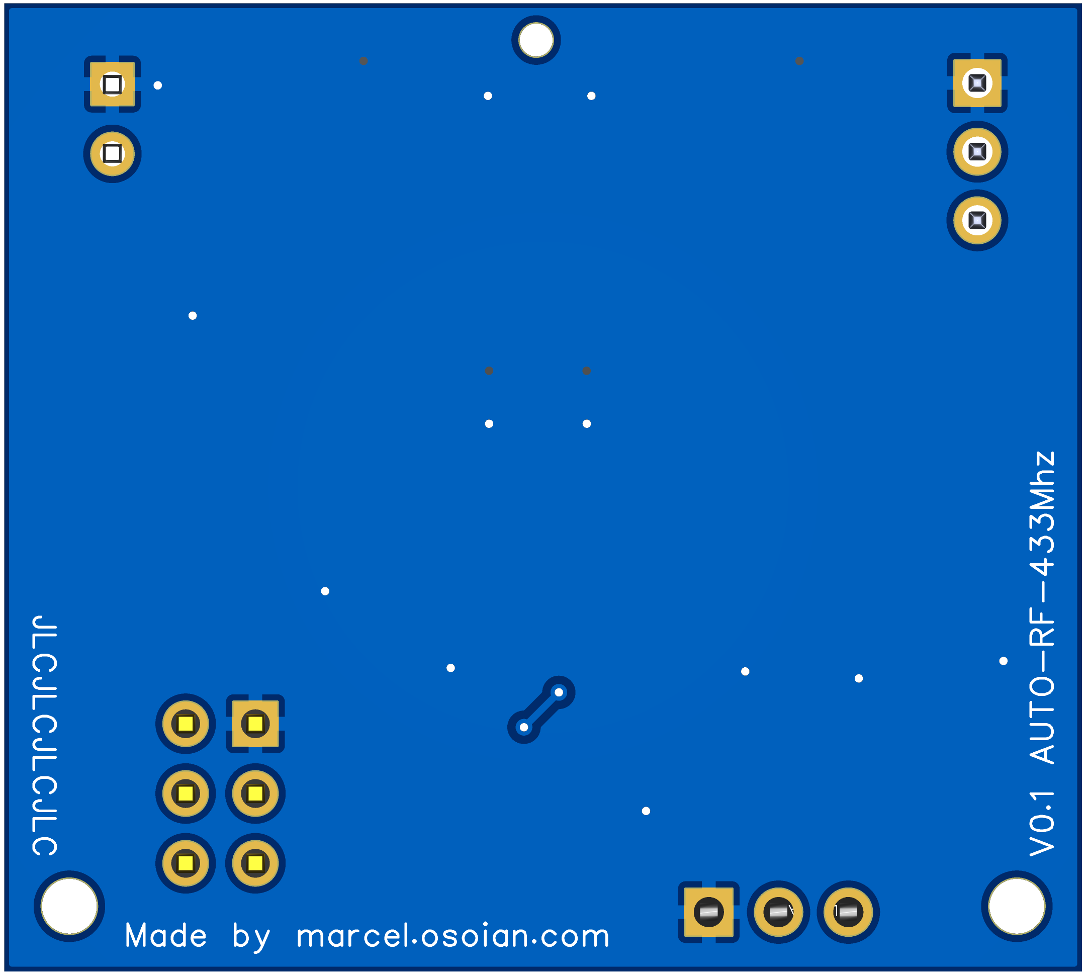


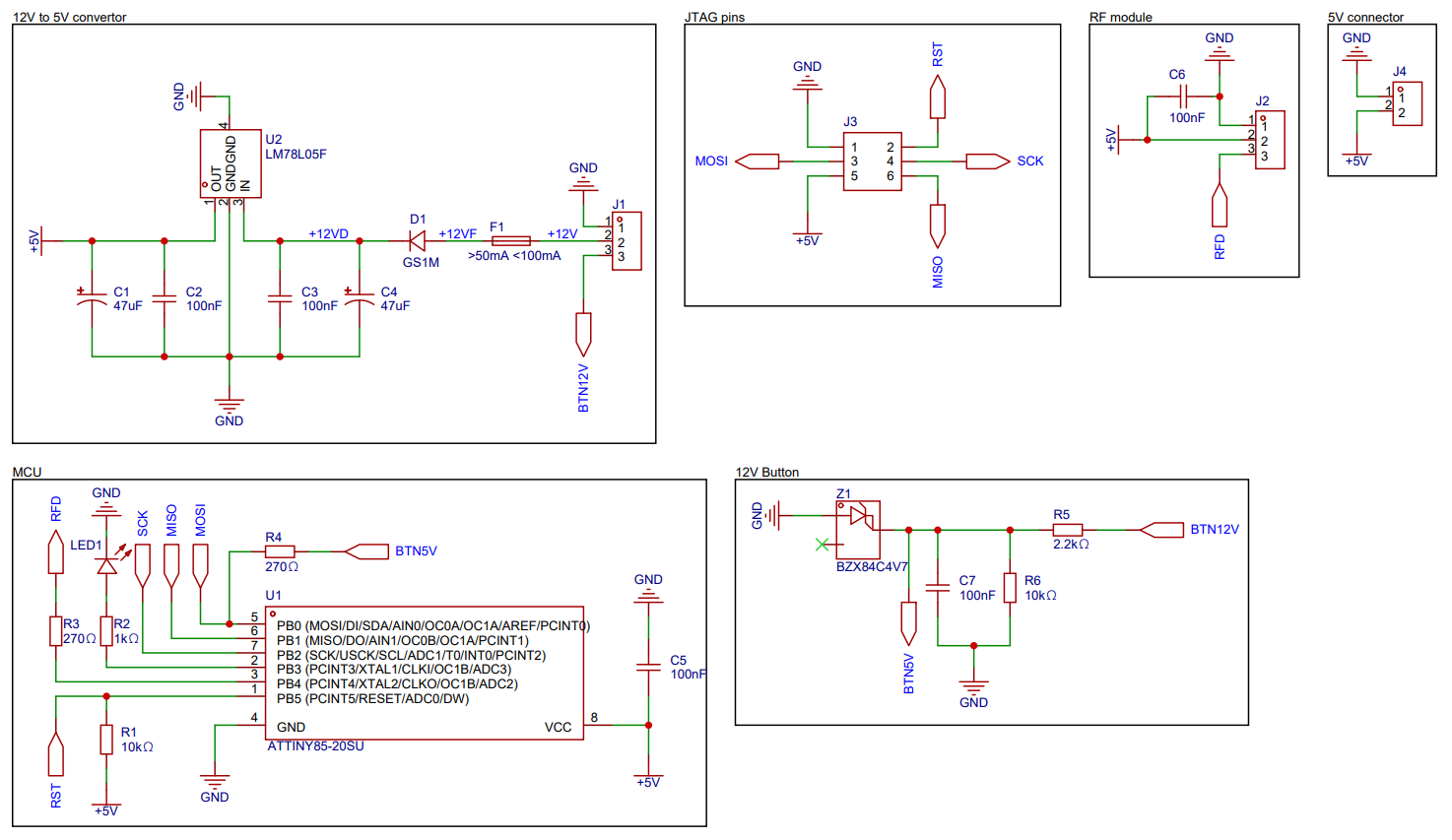
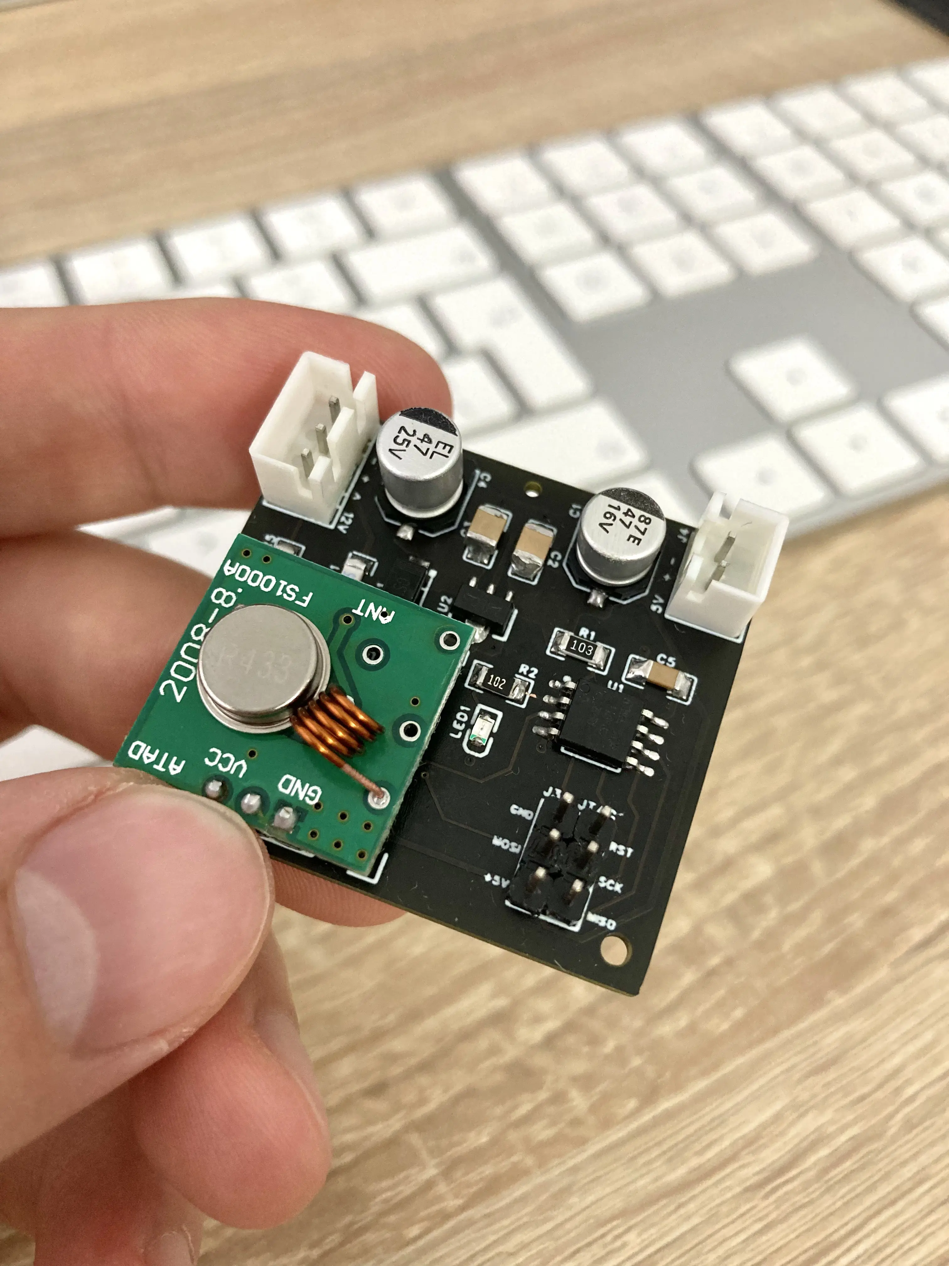
The device is powered and controlled via the connector J1, where the pin 1 (top, left) is GND, pin 2 is VCC, and pin 3 is the input pin. The input pin (3) is expected to be connected to a car button (which usually supply ~12v during pressing). Once the device is triggered via the input pin (high level signal), the device will send the RF signal repeatedly (number of repeats are defined in the code). Each time the sending is triggered, the signal will be different (the radio signals are defined in the code).
Warning: The device does not have an RF receiver, so it can not scan/copy an RF signal from an existing remote, so you need to do the reverse engineering of the RF signal and to add it manually in the code. If the device gets popularity, I’ll add this feature in the next versions.
- The device is not designed to be powered from the 5V connector (J4). The 5V connector was added to the PCB mostly for debugging purposes, but it can also be used for powering a low power device with maximum current of 50mA (the higher current may overheat the voltage regulator);
- You can try to power the device via 5V connector, but you risk damaging the voltage regulator because of reverse current (OUT → IN). For more information, check the LM7805 Datasheet (section: Application and Implementation);
- During programming the MCU, power the device via J1 connector and disconnect the 5v pin from the programmer (JTAG). I tested to power and program the device from JTAG and all went ok, it's up to you;
- In the current PCB version, the MCU sleep mode can not be implemented, because the pin INT0 is triggered with high level signal, which can not wake up the MCU (attiny85) from sleep mode (check the datasheet about low level interrupt on INT0);
- While idle, the device consumes 9mA, which may be too much for some car batteries, so to exclude the risk of draining the battery, the device has to be powered from ACC power line (the power is provided only then the ignition/engine is on).
- Add a diode between OUT and IN pins of LM78L05, to protect it from damaging by reverse current (to exclude the risk of damaging during powering from 5V connector or JTAG connector);
- Power the radio transmitter module with 12V (not 5V) to improve the range of radio signal;
- Solder an antenna to the radio module;
- Trigger the input pin by ground, which will reduce the number of components on PCB and also will make possible to put the MCU in sleep mode and wake it up by low level signal, which will reduce the power consumption significantly;
- Use smaller SMD components to reduce the PCB size (1206 → 0805);
- Move the fuse component in another PCB place or use a SMD fuse holder, to simplify the replacing;
- The lithium capacitors can be replaced with high-value ceramic capacitors, which will reduce the PCB size significantly;
- Design a nicer PCB layout.
- Microchip Studio - IDE for developing AVR microcontroller applications;
- AVRDUDE - utility to program AVR microcontrollers;
- EasyEDA - online PCB design tool (Pro Edition);
- Fusion 360 - 3D modeling tool (personal use);
- Ultimaker Cura - 3D slicing software.
- USBASP programmer - USB programmer for Atmel AVR controllers;
- 3D Printer - Ender 3 Pro;
- SH72 - soldering iron;
- Instrustar - USB Oscilloscope (for debugging and reverse engineering RF signals);
- KPS305D - DC power supply.
Contributions to the project are always welcome!
If you have an idea, or you want to report any bugs or issues, please do it through the issue tracker.
This is a hobby project by an enthusiast, not a professional.
The device comes with no warranty. Everything that you do, you do at your own risk.
If you find this repository useful, please give it a star to show your support for this project. 😊
All contents of this repository are licensed under the MIT license.


