opensolarproject / ospcontroller Goto Github PK
View Code? Open in Web Editor NEWESP32 Smart Solar Charger - the Open Solar Project
Home Page: https://github.com/opensolarproject/OSPController/wiki
ESP32 Smart Solar Charger - the Open Solar Project
Home Page: https://github.com/opensolarproject/OSPController/wiki
Is the analog input not needed when using an DPS5005. i only found a description regarding the connection with a DROK.
See ARDUINO PWM SOLAR CHARGE CONTROLLER ( V 2.02):
Why Temperature monitoring is Required?
The battery’s chemical reactions change with temperature. As the battery gets warmer, the gassing increases. As the battery gets colder, it becomes more resistant to charging. Depending on how much the battery temperature varies, it is important to adjust the charging for temperature changes. So it is important to adjust charging to account for the temperature effects. The temperature sensor will measure the battery temperature, and the Solar Charge Controller uses this input to adjust the charge set point as required. The compensation value is - 5mv /degC/cell for lead-acid type batteries. (–30mV/ºC for 12V and 15mV/ºC for 6V battery).The negative sign of temperature compensation indicates an increase in temperature requires a reduction in charge set point. For more details, you may follow this article.
Hello, I already had some esp32 lying around so I bought the power supply to build myself a small scale solar system for my balcony but I can't figure how to make this works.
I have my esp32 flashed with its input connected to a 12v power supply (for testing) and the output connected to an almost full 12v lead acid battery, here are the values reported on the web interface:
{
  "collapses":"0",
  "currFilt":"0.00",
  "involt":11.75,
  "outcurr":"0.00",
  "outpower":"0.00",
  "outputEN":"1",
  "outvolt":"12.03",
  "state":"full_cv",
  "wh":"0.00",
  "prefs":{
    "adjustperiod":2000,
    "autosweep":600,
    "currentcap":8.500,
    "inPin":32,
    "lvProtect":"",
    "measperiod":200,
    "offthreshold":11.70,
    "pgain":0.005,
    "printperiod":1000,
    "psu":"drok",
    "pubperiod":1000,
    "ramplimit":2.000,
    "setpoint":0.000,
    "vadjust":27.00
  }
}
and the serial logs:
MPPT 11.8Vin -> 0.00Wh PSU-out[11.99V 0.00A]-lim[14.71V 0.00A] ENABLED CLPS [pub-7]
MPPT 11.7Vin -> 0.00Wh PSU-out[11.99V 0.00A]-lim[14.71V 0.00A] ENABLED CLPS [pub-1]
MPPT 11.8Vin -> 0.00Wh PSU-out[11.99V 0.00A]-lim[14.71V 0.00A] ENABLED CLPS [pub-1]
MPPT 11.8Vin -> 0.00Wh PSU-out[11.99V 0.00A]-lim[14.71V 0.00A] ENABLED CLPS [pub-1]
(note the 0.00A current)
I tried to do a manual sweep:
SWEEP START c=0.000, (setpoint was 0.000)
First coming out of collapse-mode to clim of 0.00A
restore took 0.0s to reach 11.7V [goal 11.7], setting 0.0A
state change to sweeping (from mppt)
starting sweep
SWEEP DONE but zero un-collapsed points. aborting.
restore took 0.0s to reach 11.8V [goal 11.7], setting 0.0A
state change to mppt (from sweeping)
MPPT 11.8Vin -> 0.00Wh PSU-out[11.99V 0.00A]-lim[14.71V 0.00A] ENABLED CLPS [pub-2] COLLAPSED[4]
MPPT 11.8Vin -> 0.00Wh PSU-out[11.99V 0.00A]-lim[14.71V 0.00A] ENABLED CLPS [pub-8]
MPPT 11.8Vin -> 0.00Wh PSU-out[11.99V 0.00A]-lim[14.71V 0.00A] ENABLED CLPS [pub-7]
before that it said it was in constant current mode but with a current of 0.00A
I am not sure how it should work, the settings I manually set are:
if I disconnect the esp32 and set the drok output manually to 14.70V with a 2A limit (which is the charging limits written on this battery) I see some current flowing.
Did I miss something ?
I was surprised to notice that converter's lcd comes powered on even if only connect battery to the output (and input is empty (or panel covered with blanket).
Attaching MQTT Explorer screenshot with few comments With everything connected, as soon as I turn on the converter (click OK button), the involt drops to about same level as battery voltage, which is also equal to outvolt.
If I disconnect the battery - the involt jumps up to 18-20V what's measured at solarpanel output. And the outvolt jumps to the voltage value set on converter (I had it manually set to 14V).
Can't make my head around - is it the expected voltage drop = equalize to the batteries level at both sides. Or little drop at input would have been expected, but not to the battery level?]

Dear Tim, Thank You for time and efforts putting together the design, documentation and sharing the code. Much appreciated! I'm a newbie in the Solar business, sorry if stupid question. Do I understand it right that your OSPController takes care of a charge current and voltage, but does not otherwise monitor the health of battery - e.g. shutting off the appliances if battery discharged too low and panel not generating anything (night).
I'm planning solar power for my shed, including battery for evenings and a little ac inverter. I do like your approach a lot. Trying to understand what (if anything) I need in addition for safe battery operation. Thank You!
OSP running on esp, all good. If I send outputEN=0 command, can see power icon turning red on the dps, but after few sec is back green again.
Same behavior if turning off via button on dps - it turns off for few sec and then automatically back on.
https://photos.app.goo.gl/REyUWzowwa91pwYRA
Expected would be that after outputEN=0 it stays off.
My use case is for overvoltage protection - if any of lifepo4 cells above 3.6v then cutting off output. Temporary workaround - using currentcap=0 and then setting it back after safety period.
| cppcheck | LOW | STYLE | CWE-398:Class 'PowerSupply' has a constructor with 1 argument that is not explicit. | …1/lib/MPPTLib/utils.h:12:5 |
|---|---|---|---|---|
| cppcheck | LOW | STYLE | CWE-398:Class 'PubSubClient' has a constructor with 1 argument that is not explicit. | …src/PubSubClient.h:117:4 |
| cppcheck | LOW | STYLE | CWE-0:The function 'write' overrides a function in a base class but is not marked with a 'override' specifier. | …src/PubSubClient.h:170:19 |
| cppcheck | LOW | STYLE | CWE-0:The function 'write' overrides a function in a base class but is not marked with a 'override' specifier. | …src/PubSubClient.h:173:19 |
Translate???
I've had this built and running for awhile now but would like to discuss it further. The Discord link has expired.
Would you be able to update the link or add one without expiration?
Thanks!
Great project! Unfortunately, I was unable to gather how the ESP32 is connected to the converter. You mention for labeled pins on the converter, but not how they connect to the ESP32. It would be great to have a sentence on that.
While I'm here, I am an EE with power conversion experience and I agree this is an MPPT despite comments from others. It seems you achieve MPPT because you are controlling for input peak, and output regulation suffers - which is a fine approach if the load can tolerate it. I'd like to throw my support into the hack-a-day comments and first would like to better understand the connection to the converter, and also to confirm what you are controlling (by the code it seems you are changing the load current) Is there an API to the converter UART you can point us to? Thanks!
Hi
I really hope this project isn't dead.
flash with esptool.py: esptool.py --chip esp32 --port /dev/ttyUSB0 write_flash 0
This will flash successfully, but monitoring the output only gives:
rst:0x10 (RTCWDT_RTC_RESET),boot:0x13 (SPI_FAST_FLASH_BOOT)
invalid header: 0x04030000
invalid header: 0x04030000
invalid header: 0x04030000
invalid header: 0x04030000
invalid header: 0x04030000
invalid header: 0x04030000
invalid header: 0x04030000
ets Jul 29 2019 12:21:46
(repeats)
The nodemcu-32 is brand new.
Couple issues:
pio device monitor and gnu screenFuture wishlist:
I try to find project similar to OSPController for wind turbines but without success. So is it possible to adjust this project to handle low power wind turbine (300W DC)?
as psu shuts off (during night), the output parameters (outputEN, outputvolt) in mqtt and webserver should reset back to 0
Currently it keeps ENabled=1 and last output Voltage value, which, I believe is wrong behaviour as normally you can't even change the outputEN from serial/curl/mqtt
As I can understand the main communication protocol is UART, and the ESP8266 (ESP01) easily handle that , it will cost less and can be more portable.
This is the console output after fresh upload from vsc, sending wifiap and wifipass and doing save and restart.
I had provided ap and pass several times (and also verified from simple arduino code that it is working/letting to connect).
(it is dark outside and I don't have drok connected - that explains psu fail)
loaded key PSUperiod to 2000
loaded key autostart to false
loaded key autosweep to 600
loaded key currentcap to 8.500
loaded key measperiod to 200
loaded key mqttFeed to solar/mppt
loaded key mqttPass to
loaded key mqttServ to
loaded key mqttUser to
loaded key pgain to 0.005
loaded key printperiod to 1000
loaded key pubperiod to 1000
loaded key ramplimit to 2.000
loaded key setpoint to 0.000
loaded key vadjust to 116.50
loaded key wifiap to aaaaaa
loaded key wifipass to 12345678
finished setup
6.9Vin -> 0.00Wh <0.00V out 0.00A 0en>
wifi event
wifi event
0.0Vin -> 0.00Wh <0.00V out 0.00A 0en>
0.0Vin -> 0.00Wh <0.00V out 0.00A 0en>
wifi event
can't pub connect, wifi 0 pub 0
can't pub connect, wifi 0 pub 0
0.0Vin -> 0.00Wh <0.00V out 0.00A 0en> [pub disconnected]
wifi event
psu update fail
0.0Vin -> 0.00Wh <0.00V out 0.00A 0en>
0.0Vin -> 0.00Wh <0.00V out 0.00A 0en>
can't pub connect, wifi 0 pub 0
0.0Vin -> 0.00Wh <0.00V out 0.00A 0en> [pub disconnected]
0.0Vin -> 0.00Wh <0.00V out 0.00A 0en>
wifi event
psu update fail
0.0Vin -> 0.00Wh <0.00V out 0.00A 0en>
can't pub connect, wifi 0 pub 0
0.0Vin -> 0.00Wh <0.00V out 0.00A 0en> [pub disconnected]
0.0Vin -> 0.00Wh <0.00V out 0.00A 0en>
wifi event```
I offer Photography not Incongruent ambiguity (hopefully)
I have got the code on the esp but it doesent want to connect any networks or anything I can get a log
though I see the latest code reflects the updated board platformio.io data, it seems that while a glance at the code would conform to the simple enough principal at hand, and its not like you can go hold everybody's hand and patently walk thru the nitty gritty, right? So!
That's where I come in, so I see the instructions are well written and concise is good, please! Brevity
but I see the pin change from 36 to 32 is that right?
Its must be since no such pin exists on the nodemcu esp32 unless your talking about the esp32-wroom and i see the photo on the roof depicts a close shave with some hairy looking jumper nest work and I would just love to know exactly what board and pins we were looking at, tho its not like I couldn't meet the RX tx and involt requirement if that's really all the connections needed?
9 Only reading one pin for involt,? which is I assume the battery meter
The updated links are greatI
think your layout accounts for the right amount of facts and does a moderate to fair job of conveying in no uncertain terms the often detailed if sometimes incomplete array of materials and pertaining operations, however I would really like to see some fine to the point labeling and description.
I have been struggling with my understanding of exactly how and where everything is all connected. I understand this is git not Instructables or Hackaday and the focus is on the code over often erroneous explanation
One capacitor reads 105 while the other is backwards and looks smaller would love the deets!
Hey this is a really neat build and I gotta say for what you've got its my delight if I might take photos and or draw a pin for pin schematic..
How ever you see fit to share, much appreciated and I would prefer my critical, poorly informed and exceedingly inexperienced notes be viewed as my vehement will to contribute effectively.
The mppt stuff looks great but I can't tell my arse from a serial port
How does your PSupply survive, given https://www.droking.com/cs/support/topic/backdriving-the-200310-as-a-solar-battery-charger/.
Mine didnt.
Hej
I wasn't able to send any command through the serial terminal. I get a lot of feedback from the ESP32S about whats wrong with the voltages and so on. But it doesn't accept any commands.
So I've tried to build the project in PlatformIO. The available binary seems to be outdated anyways.
Unfortunately this is also not possible.
I get this message :
In file included from lib/MPPTLib/solar.h:2, from src/main.cpp:1: lib/MPPTLib/publishable.h:3:10: fatal error: FreeRTOS.h: No such file or directory
But regardless of which version of FreeRTOS I try, it will never compile.
I think this is a great project and I would really like to help with improving the documentation. I think it's missing a lot of things for people who are not so deep involved in programming but more in electronics. But first I need to get my system up and running. ;)
My Setup is a ESP32S with a DPS5020
I have all the parts ready for solderong :) However, my input voltage is 48V. I will drop down to 42V in order to mainly charge electric skateboards :) Can you point out where I need to tweak your setup in order to work with approx. 48V. I see the voltage divider must be different, I am thinking to put small dc-dc converter there too so I can adjust if I change my panels condiguration. Cirrently its 4 panels in series. Do I need to modify the software?
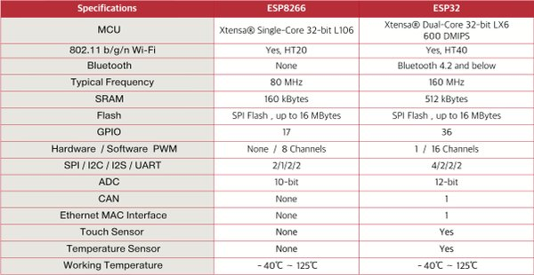
Sadly the ESP01 doesn't have an ADC and we need one to measure the solar panel input voltage.
An ESP8266 has one ADC channel with 10bit resolution so it may work, but the little extra resolution of the ESP32 and far more flexibility made it an easy choice. The ESP32 has 12 bit resolution (0-4096).
So the answer is yes ??
Comparison - note ESP32 has bluetooth. What is the concern about flexibility?
Right now the web interface is limited to a json system output and allows POST of configurable things. Ideally in the future:
outCurr_, limitCurr_ and setCurrent needs scale adjustment for DPS5020 (/1000 for DPS5005, but /100 for DPS5020)
Two suggestions.
First - either in software setup or Hardware - setting up the ESP, where it talks about voltage divider
Fine tune vadjust value - test Voltage from panel using multimeter.
Second - Hardware Build
Setting up the PSU
amend/update with instruction to enable "auto-output"
Keep pressing "SET" to enter parameter setting interface; press "Up" to adjust to "-F2-". Then press "OK" and it will display "Yo-0". Switch it to "Yo-1" by pressing "Up". Press "OK" to store the setting.
For the DPS5015 the scale should also be adjusted to /1000.
I changed the DPS::begin() function in powersupply.c:
dps5020_ = (model == 5020 || model == 5015);
Looks to me line 109 missing "{" at the end and line 115 missing "}" at the beginning.
OSPController/lib/MPPTLib/solar.cpp
Lines 109 to 115 in 528c944
Asis it is giving the connect error message even in case of successful connect.
How about adding a Wiki page on the basics of your MPPT tracking algorithm?
I wonder, would it make sense to stop actively working with PSU after the sunset and before sunrise?
May still checking&reporting battery voltage (outV) at some interval, but deepsleeping the rest of the time?
If doing so, I guess, it should request sun-triggers based on configured latitude/longitude (e.g. in a similar way how Tasmota does it)
A declarative, efficient, and flexible JavaScript library for building user interfaces.
🖖 Vue.js is a progressive, incrementally-adoptable JavaScript framework for building UI on the web.
TypeScript is a superset of JavaScript that compiles to clean JavaScript output.
An Open Source Machine Learning Framework for Everyone
The Web framework for perfectionists with deadlines.
A PHP framework for web artisans
Bring data to life with SVG, Canvas and HTML. 📊📈🎉
JavaScript (JS) is a lightweight interpreted programming language with first-class functions.
Some thing interesting about web. New door for the world.
A server is a program made to process requests and deliver data to clients.
Machine learning is a way of modeling and interpreting data that allows a piece of software to respond intelligently.
Some thing interesting about visualization, use data art
Some thing interesting about game, make everyone happy.
We are working to build community through open source technology. NB: members must have two-factor auth.
Open source projects and samples from Microsoft.
Google ❤️ Open Source for everyone.
Alibaba Open Source for everyone
Data-Driven Documents codes.
China tencent open source team.

