Versatile, cheap, portable and robust USB to GPIB converter (USBTMC class based).
You'll find many projects like this, but this one is special (ok, everybody will claim this) :-)
If you have a lot of test equipment at home, you might know the issues: Lots of devices only have GPIB as interface and the GPIB adapters and GPIB cables on the market are very expensive and some of them even have many issues, when run under Windows 10 (device driver does not work). Or they e.g. are not able to be operated with VISA, because they are UART based, need special command sequences, ...
Apart of the 2 very big manufacturers, other GPIB adapters, e.g. with Ethernet or also USB interface are not recognized my normal VISA providers or PyVisa, making the measurement control implementation specific for your GPIB adapter.
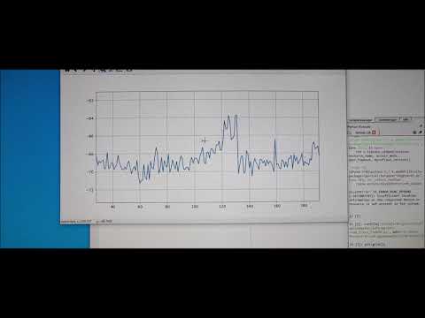
I've got frustrated and tried to turn it into something positive - Here a video showing the final device in action - click to view:
Some goals of the project were:
- Work based on the standard USBTMC protocol. This allows the GPIB test equipment to look like a normal USB based measurement device and work flawless with e.g. NI VISA, Labview, Matlab or PyVisa.
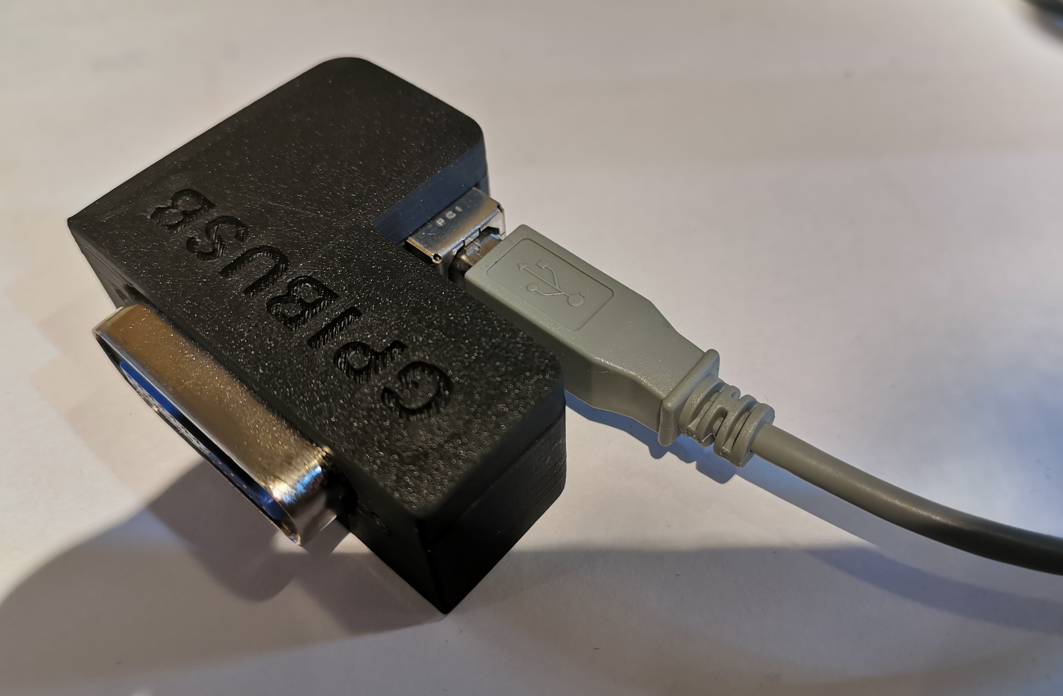
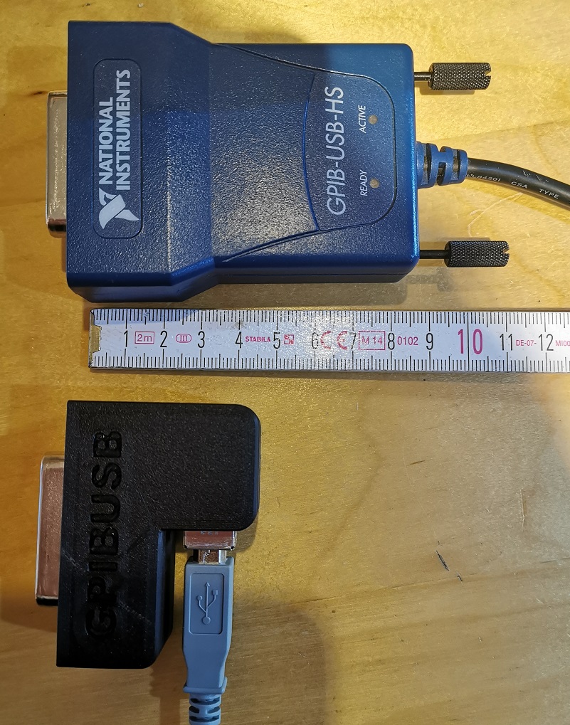
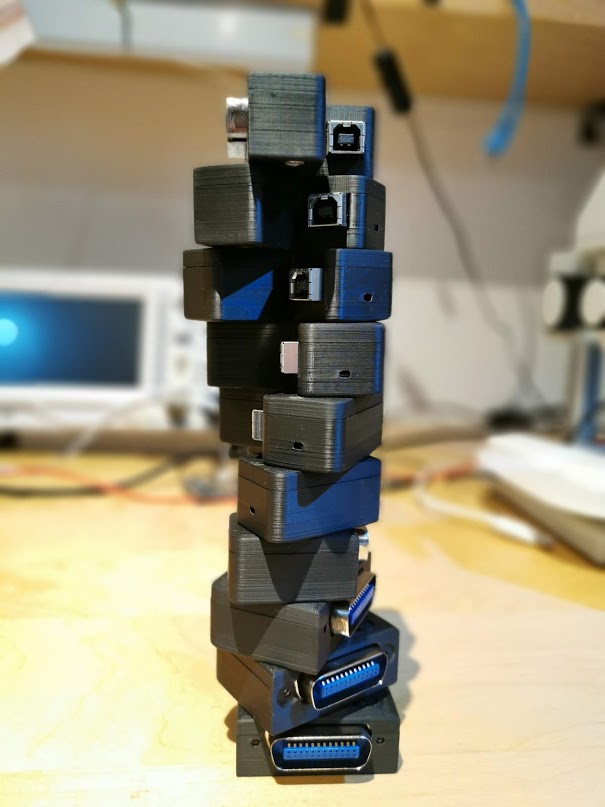
- Have a small length - otherwise my eqipment has the risk of falling from the shelf :-) Also the USB cable should connect 90 degree angled, to make it very short.
- It should be cheap but still versatile (you can build a single one of these for only 14 USD!)
- It should support ALL my test equipments, from many different GPIB implementation generations and different GPIB flavors
- The Firmware should be upgradeable over USB
- It should be rock-solid (!) I don't want to end up in a very long measurement beeing interrupted because of a software issue of my USB GPIB converter.
- It should support additional features like serial poll, remote enabling/disabling
- If there is no GPIB device connected to the USBGpib converter, or the GPIB device is powered down, there should be no USB device visible on the PC.
All those goals are met.
A version 2.0 of the original HW & SW is in the pipeline. This is mainly to address the unavaiability of ATMEGA32U4 in TQFP at the moment. There are however Arduino boards from that you can desolder them. Those are sometimes in QFN, so the PCB now supports QFN and TQFP housings. Additionally I'll make an AtMega16U4 SW variant without bootloader, because AtMega16U4 is available still right now. Note that I changed the package sizes also of the 0402 components to 0603 for easier soldering.
In case you use an AtMega32U4 this board is still fully compatible with the current version of the software!
Due to very low bandwidth for such kinds of projects it will take a while until I have the AtMega16U4 firmware ready and tested.
Allthough I typically would prefer nowadays an ARM Cortex M0/3/4/7 controller, there is an issue with it. Available devices support only max. 3.3V supply voltages, such that there would be a requirement for a level shifter towards the GPIB Bus. GPIB is based on 5V (not exactly true, but a first iteration).
This limited the microcontroller choice to e.g. AVR or PIC controllers. Because of very good availability I ended up in ATMEGA32U4 controllers. Apart of the device supporting 5V I/O voltages, it also does not require a regulator to be part of the application - it has an internal 3.3V regulator. This minimizes the full application schematic and BOM.
Apart from that, there is an excellent USB stack available http://www.fourwalledcubicle.com/LUFA.php.
The GPIB side of the schematic can be directly connected to the ATMega32U4 IO pins. The IO pins from the microcontroller side are only set to 2 different states: Tristate (input) or output LOW, to talk over GPIB.
All components are easy to source, so I only specify the potential critical ones:
- 16 MHz Crystal: Farnell 2853867 - MCSJK-7E-16.00-8-30-100-B-30
- GPIB connector: Farnell 2421095 - NORCOMP 112-024-113R001
- USB connector: Farnell 2668483 - Amphenol ICC 61729-1011BLF
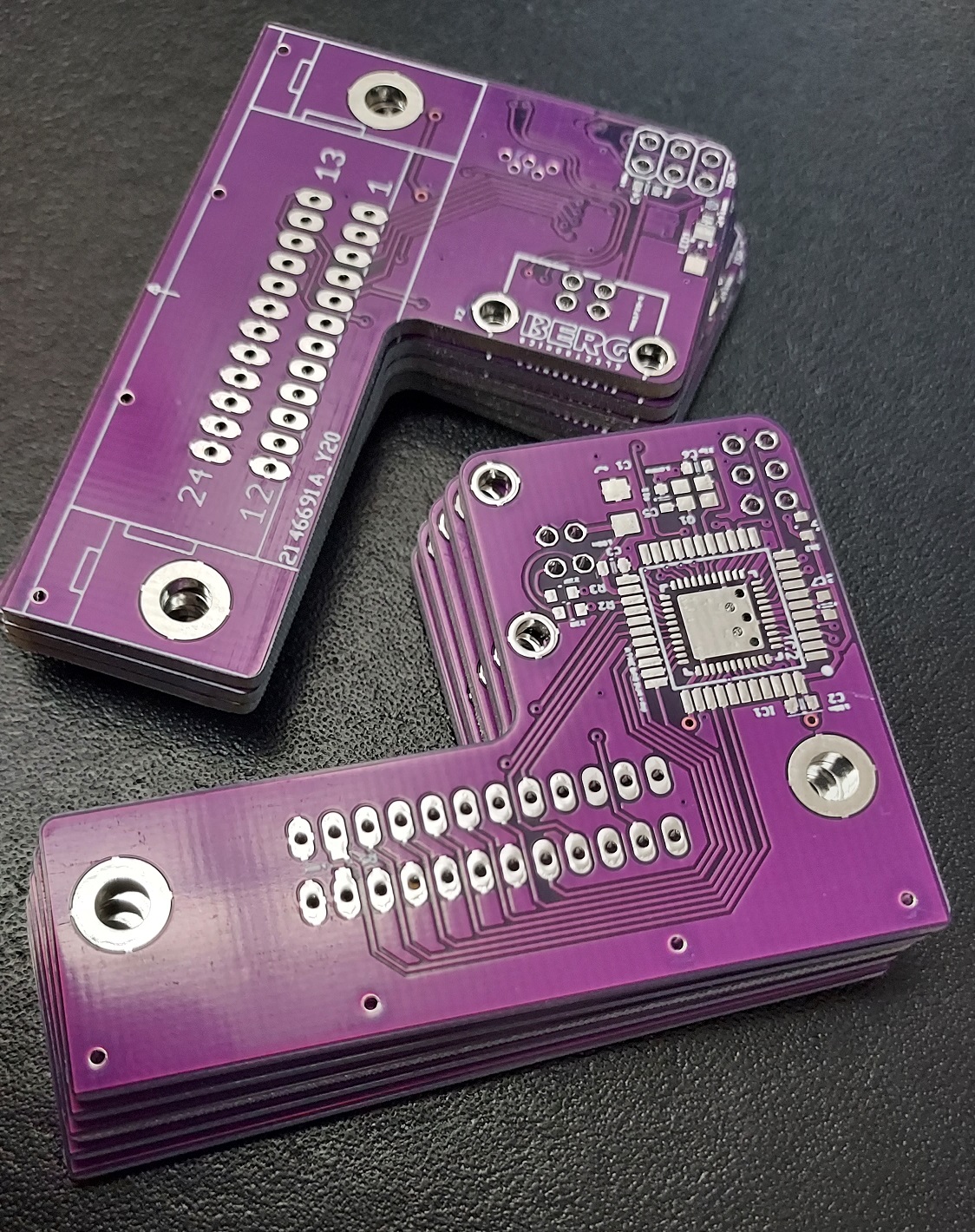
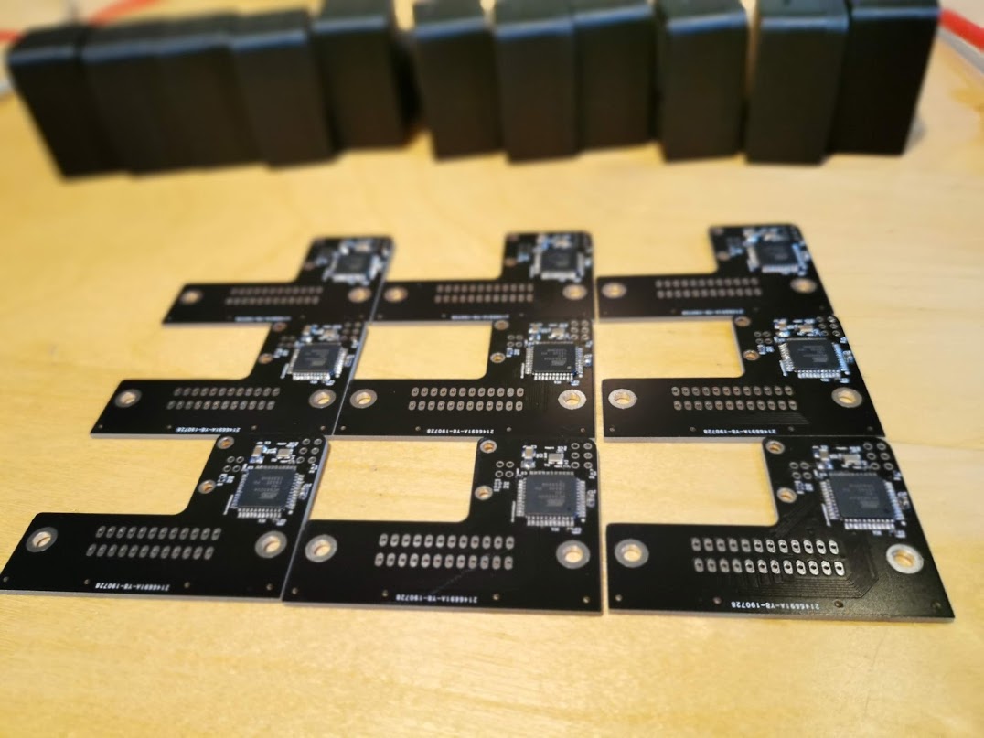
The PCB can be ordered at nearly any PCB pool production service (e.g. 10 PCBs for 2 USD + shipping). The gerber files are included in the "HW/Gerber files" subdirectory.
Mounting is fairly simple, as there are no extremly small components. I suggest to mount first all the SMD components, followed by the bulky connectors.
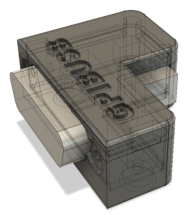
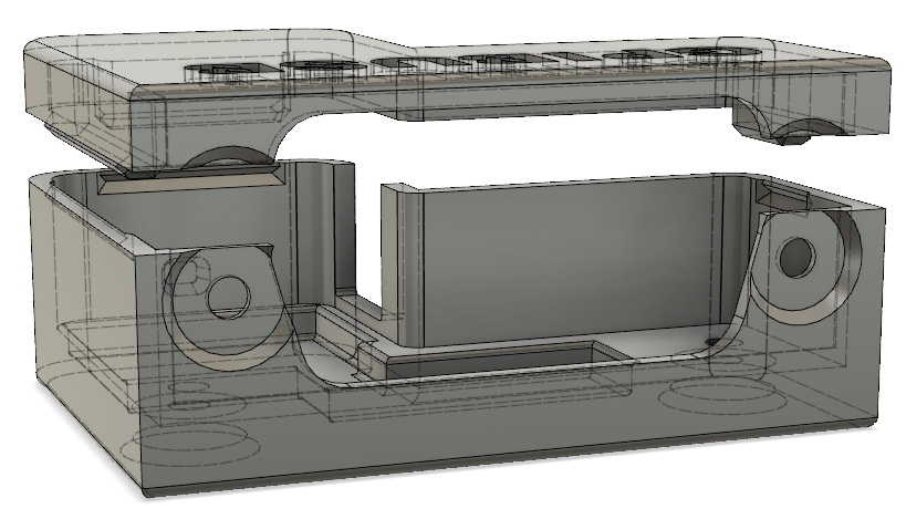
I created a sophisticated 3D printable housing for this adapter. The design was made with Fusion 360. The project file + the STL files are included in the "Housing" subdirectory.
The PCB fits perfectly into it. Optionally it can be fixed with 2 mounting screws (the GPIB connector has 2 threads, use 2 times 4-40 UNC x 3/8) and the TOP cover snaps onto the housing base.
I printed this using an Ender 5 3D printer with black PLA, 0.15mm layer height, 1mm wall thickness, no support. Take care, that you rotate the TOP part of the housing by 180 degrees, so that the flat side is located on the printer bed. Printing works fine, several iterations of the design were made to ensure good printability. I printed so far 15 housings, without a single fail.
The source code of the Boot loader (slightly modified LUFA MassStorage Boot loader) and the main USBGPIB converter are located in the "SW" subdirectory. At the time of publication LUFA 170418 release was used, with GCC as compiler.
For those, that just want to create their own device, I've included the binary output in the "SW/binaries" subdirectory.
For initial programming an AVR ISP adapter is needed to program the "Bootloader.hex" file.
It is very important, that the Fuses of the AVR are programmed.
Here an example how to program the bootloader using avrdude (using usbasp programmer): avrdude -c usbasp -p m32u4 -e -Ulock:w:0x3F:m -Uefuse:w:0xcb:m -Uhfuse:w:0xd8:m -Ulfuse:w:0xff:m avrdude -c usbasp -p m32u4 -U flash:w:BootLoader.hex
After programming the file, disconnect and connect the device and a USB drive will show up. Copy the TestAndMeasurement.bin file to this USB drive - ideally using the command line. Example: copy TestAndMeasurement.bin F:\FLASH.BIN.
On Linux, there is a bug with the LUFA mass storage that means it is required to use dd if=TestAndMeasurement.bin of=/mnt/FLASH.BIN bs=512 conv=notrunc oflag=direct,sync.
When done, disconnect and connect USB again and you're ready to use it!
To enter the boot loader at later stages for updates, short circuit the 2 pins of the ISP header, as shown in below picture for about 3 seconds:
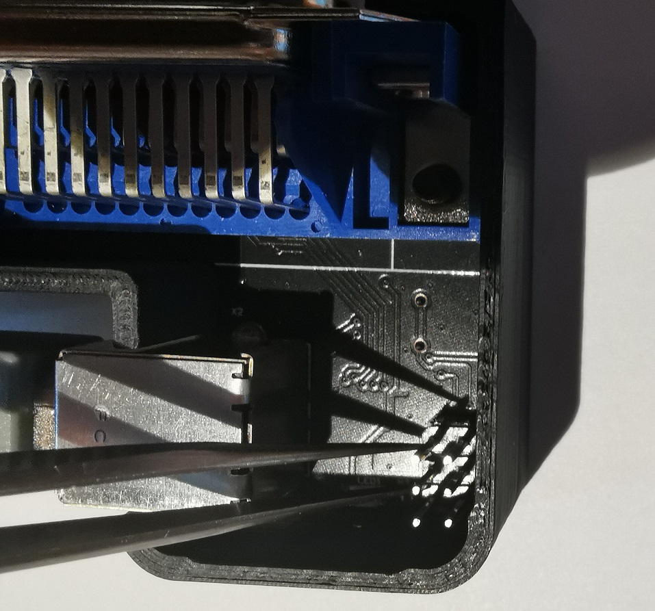
Afterwards, a USB drive will show up and you can copy the firmware again to the device, as described in the previous section.
You might be surprised initially, that the device does not show up in your device manager (or lsusb), when you connect only the USB side. This is a feature, not a bug (really!). Only, if a GPIB device is connected, you can see the device on your PC too.
The reason behind the feature is simple: Instead of having a standard GPIB wiring, where you have a single GPIB controller and lots of GPIB devices interconnected, USBGPIB supports only a direct connection of the USBGPIB device to your measurement device. If you have like me e.g. 14 Instruments you don't want all to show up in the device manager, if the measurement device itself is powered down - you won't anyway be able to communicate with a powered down device.
When USB and the GPIB side is connected, the device enumerates. The USBGPIB device reads out the ID of the instrument and constructs a unique USB Serial number out of it. It is thus easily possible to assiate multiple connected USBGPIB devices with the measurement instrument.
The VISA ressource name is constructed from this USB Serial number. You can identify easily e.g. in NiMax, which device is connected:
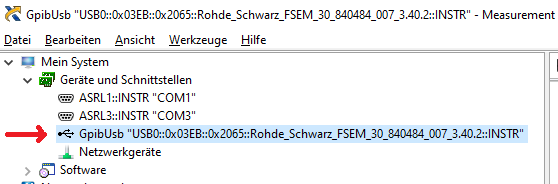
If you connect your USBGPIB device afterwards to another GPIB measurement device, it will disconnect and connect with a new serial number string, matching the other GPIB device *IDN? response again.
GPIBUSB does probe all GPIB primary addresses (and secondary address 0) for presence of a GPIB Talker/listener. It is thus not required to set a specific GPIB address - GPIBUSB will find it itself.
The only importance setting on the measurement device is, that the GPIB interface is enabled, which is typically the case.
The LED indicates different states:
LED blinking: The USBGPIB converter is connected to a measurement instrument, it is powered off or its GPIB port is disabled. In this state, the device is also not connected to USB and will not show up in the device manager or lsusb. LED on: The device is connected to a measurement device and GPIB communication possible. It is also accessible over USB LED off: The device is not connected over USB, or the PC powered off :-)
As this converter implements the standard USBTMC Test and measurement class, you can control your instrument from ANY of the normal VISA tools. I tried so far R&S VISA and NI Visa, using Python and Matlab to talk to the devices.
- R&S FSEM30
- R&S SMIQ03
- R&S CMU200
- R&S SMW200A
- R&S FSW
- R&S FSV
- Keithley 199 multimeter
- HP 3325A synthesizer/frequency generator
- HP 3457A multimeter
- Agilent E4406A VSA transmitter tester
- Tektronix TDS7104 Digital Phosphor Oscilloscope
- HP 8596A spectrum analyzer
- Agilent E3648A dual power supply
- I tested as operating systems Windows 7 and 10 so far only. But linux should also work out of the box.
- USB1.1, USB2.0 and USB3.x ports tested, with and without USB HUB in between.
- The connection stays responsive, when power cycling the PC, or hibernating/sleeping it
- Different connection cycles (GPIB side connected first, USB side connected first, swapping GPIB side equipment, ...)
- Extensive testing of timeout scenarious. E.g. making an illegal query and testing, if the USBTMC handles the timeouts properly. This was a very tricky part to get right.
- Tested special transfer modes. E.g. capturing screenshots from different equipments is usually something, which will drive other GPIB adapters to the limits, because binary data of unknown length needs to be transported successfully.
Since 26th April 2020 update, there is are additional options implemented to configure the behaviour of GPIBUSB.
First of all, it turned out, that some old test equipment is not capable to support EOI generation when reading data. So GPIBUSB would not be capable to sense, when the instrument finished talking. This old test eqipment terminates talking by generating e.g. \n (line feed) or \r\n (CRLF) or \r as termination.
To support those instruments an option to select the termination method is implemented - see section "read termination".
Furthermore it is now possible to turn off the automatic readout of the instruments *IDN? or ID? response after power on. This mechanism works fine on most test equipments, but again there is test equipment, that does not support this, which would end up in generating a different VISA ressource name every time you power on. If this automatic ID readout is turned off, the VISA ressource name will be just generated based on the detected GPIB address and the USB serial number of GPIBUSB.
All parameters are applied immediately after setting them and are stored in a non voltatile way in the EEProm of the microcontroller.
To enter the mode to set the setting the indicator pulse command has to be send to GPIBUSB followed by a textstring as explained below.
To generate a indicator pulse (which blinks the LED of only the addressed USBTMC device), the following pyvisa snippet can be used (VM is the opened VISA ressource):
VM.control_in(0xa1, 0x40, 0, 0); This makes the LED blink once, but also check, if the next command is a set parameter command, starting with '!' character.
The following read termination method options are available:
- Option 0: (default): EOI only (the normal way GPIB works)
- Option 1: EOI + \n (LF / line feed)
- Option 2: EOI + \r (CR / carriage return)
If your device terminates with \r\n, select Option #2.
To set these options execute (Pyvisa example): VM.control_in(0xa1, 0x40, 0, 0) VM.write('!01XX')
for XX enter either:
- 00 for Option 0 (EOI only) => VM.write('!0100')
- 01 for Option 1 (EOI and \n) => VM.write('!0101')
- 02 for Option 2 (EOI and \r) => VM.write('!0102')
To turn off the automatic instrument ID readout after power up, execute: VM.control_in(0xa1, 0x40, 0, 0) VM.write('!0001')
To turn on the automatic instrument ID readout (this is the default behaviour of GPIBUSB), execute: VM.control_in(0xa1, 0x40, 0, 0) VM.write('!0000')
After a power cycle the USB device VISA ressource name and USB serial number string will change, based on this setting


