Git Product home page Git Product logo

lipopi's Introduction

LiPoPi

  • Description: LiPoPi is a guide to setting up the Raspberry Pi with a LiPo battery including both running and charging it
  • Project Website: GitHub
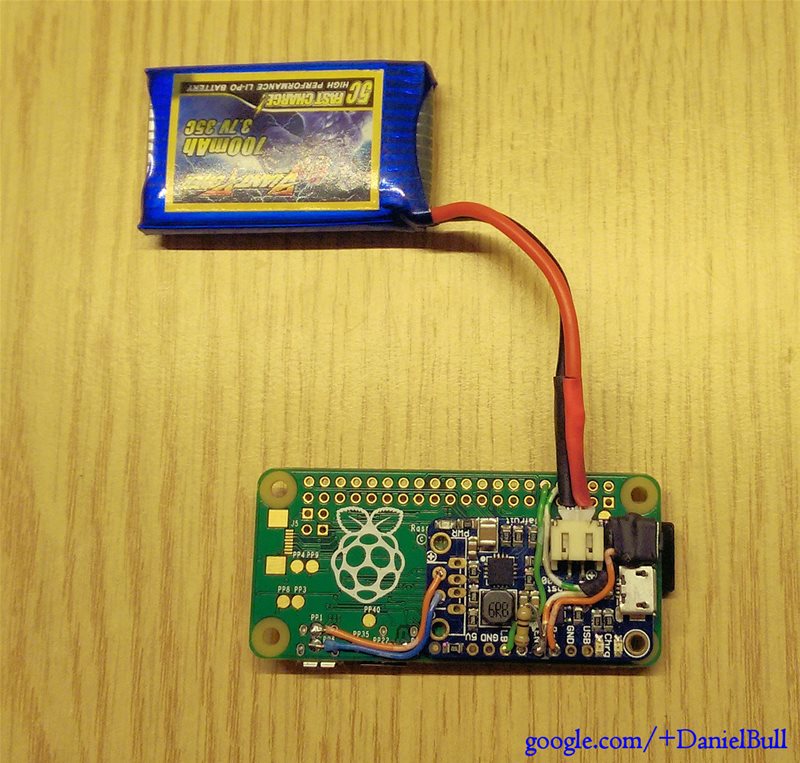
  • Requirements: A Raspberry Pi and an Adafruit PowerBoost 500 Charger or 1000C Charger
  • Skillset: Requires soldering skills and a basic knowledge of the command line
  • License: GPL Version 3

Power-Up / Power-Down Version

See this page for a version in which the push button switch can both power up the Raspberry Pi and trigger an orderly shutdown.


Advanced Version With Battery Level Monitoring

See this page for advanced version of this project which includes the features of the power up/down version above as well as battery level monitoring.


Basic Version Features

  • Push button to power up the Pi (requires a long push - good for preventing accidental starts)
  • Automatic shut off of the PowerBoost power supply after the Pi is shutdown
  • Automatic graceful shutdown of the Pi when the battery is low (to stop SD card corruption)
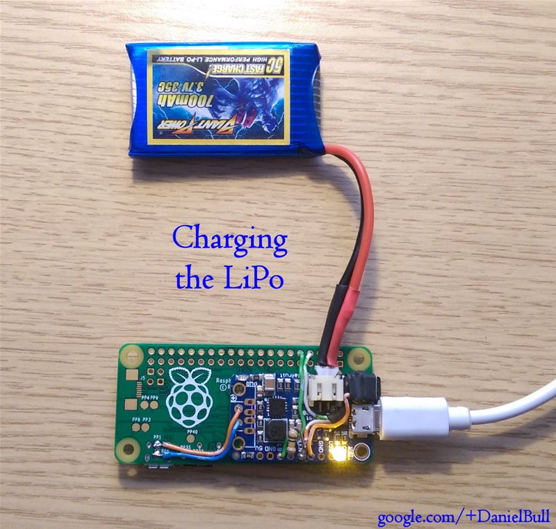
  • Single power socket to both charge and run the Pi
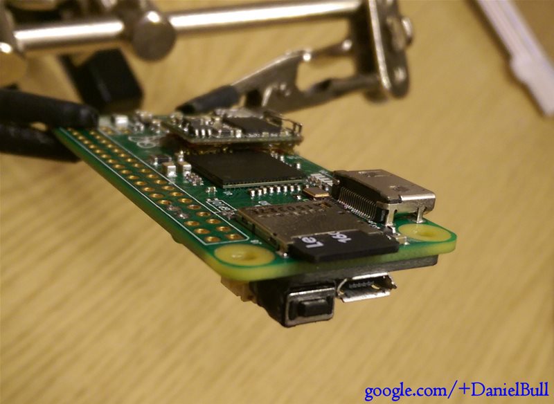
  • If using the example layout, the power button, power socket and SD card are located all on one end (makes cases nicer)

overview


How it Works

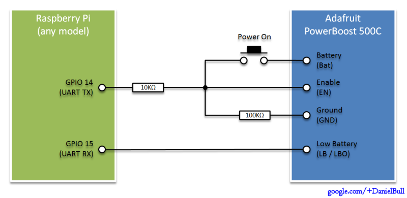
When pushed the LiPoPi power button connects the battery output (Bat) to the enable line (EN) on the Adafruit PowerBoost which then powers up boosting the LiPo's 3.7v to the ~5.2v required by the Pi. This causes the Pi to begin to boot and after about 3 seconds GPIO 14 (UART TXD) goes high (due to its unique characteristic of going to 3.3v whilst the Pi is running and back to 0v when the Pi is shut down). This then takes over the job of keeping the enable line on the PowerBoost high and the Pi remains powered up even after the pushbutton is released.

Whilst the Pi is running the PowerBoost informs the Pi of the battery status by switching the LB / LBO pin (which is connected to GPIO 15 - UART RXD) low when the battery is low. This is picked up by a cron task on the Pi which initiates a graceful shutdown making sure no data is lost and the SD card does not get corrupted. Once the Pi is shutdown (for whatever reason) GPIO 14 goes low again, causing the PowerBoost's enable line to drop and the whole system to power off.

We've had a question about how long the batteries will last, a few of you might wish to know how to calculate this. For more information see the thread here


Hardware

circuit

(Please Note: Do not connect devices which use GPIO 14 or 15 (UART/Serial) to the Pi at the same time as this circuit as they will cause your Pi to power off or shutdown)

  1. Connect the PowerBoost's 5v output to your Raspberry Pi either by soldering wires directly between the two (you can use the GPIO to power the Pi for example) or by attaching the optional USB socket to the PowerBoost and using a regular micro USB cable between the two.

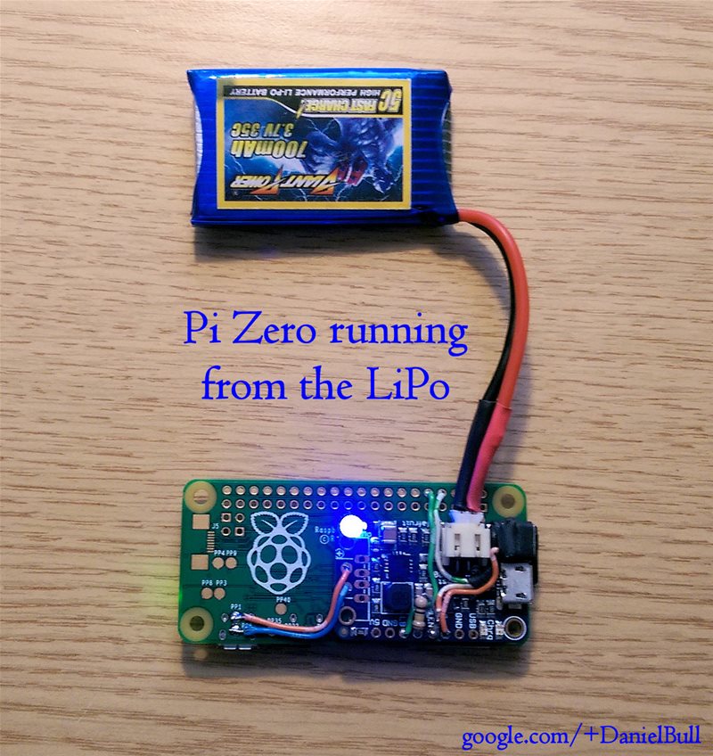
  2. Put a known good SD card in your Pi, connect a LiPo battery to the PowerBoost and check that the Pi starts up straight away and runs correctly (you may need to charge the battery first).

  3. Shut everything down and disconnect the LiPo again.

  4. Solder a 100k resistor between one of the ground lines (GND) on the PowerBoost and the enable line (EN). (See notes about Raspberry Pi 3)

  5. Connect the LiPo back up to the PowerBoost and if you have fitted the resistor correctly you will notice this time it doesn't power up on its own, this is because the resistor pulls the enable line low.

  6. Disconnect the LiPo again.

  7. Connect a pushbutton between the battery output (Bat) on the PowerBoost and the same enable line (EN) you previously connected the resistor to.

  8. Connect the LiPo back up to the PowerBoost, again the Pi should not start.

  9. Press and hold the button just long enough to check the Pi power light comes on (confirming your wiring is correct) but not enough for it to start booting (if you do accidentally go too far, shutdown the Pi before releasing the power button).

  10. Disconnect the LiPo again.

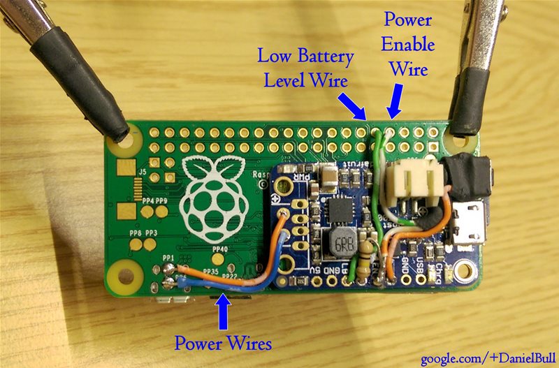
  11. Connect a 10k GPIO protection resistor between Pin 8 (GPIO 14 - UART TXD) on the Raspberry Pi and the PowerBoost enable line (EN) (the same place that the resistor and pushbutton are connected to).

  12. Connect the LiPo back up to the PowerBoost, again the Pi should not start.

  13. Press and hold the button for at least 3 seconds, the Pi should start booting. If you have done step 1 of the software instructions when you release the button the Pi should continue booting.

  14. Shutdown the Pi with the shutdown command (DO NOT use the halt command), the Pi should shut down followed by the PowerBoost shutting off.

  15. Connect a wire between the low battery line (LB / LBO) on the PowerBoost and pin 10 (GPIO 15 - UART RXD) on the Raspberry Pi, this is to tell the Pi when the battery is low (you can use a different GPIO if you prefer).


Special Note About Raspberry Pi 3

Previously unlike the other Pi's the Raspberry Pi 3's software emulated version of the UART meanst that GPIO 14 was not high by default. The way to resolve this was to enable the console which produced enough data that we could "pretend" GPIO 14 was high by placing a 100uf capacitor across the 100k resistor.

However this appears to be solved in the newer versions so you can use the Pi3 in the same way as with the other models.


Software

  1. Run sudo raspi-config and select "Interfacing Options" followed by "Serial" and answer "Would you like a login shell to be accessible over serial?" with No, followed by "Would you like the serial port hardware to be enabled?" with yes.

  2. Run wget -N https://raw.github.com/NeonHorizon/lipopi/master/low_bat_shutdown to get the example script which checks for low battery and shuts down the Pi (if you prefer you could write this in Python or whatever).

  3. Make it executable with chmod +x low_bat_shutdown

  4. If you used a pin other than GPIO 15 for the low battery line (hardware step 15), edit this file and change the pin number (otherwise you don't need to edit it at all).

  5. Execute this script by typing ./low_bat_shutdown nothing should happen. If the Pi shuts down then you did something wrong in Hardware step 15.

  6. Either leave the script in your home directory or move it to somewhere on the Pi where it wont get deleted, it needs to be run regularly by the system to check for low battery, if you delete it your Pi wont shut down!

  7. Go into the cron directory where scheduled tasks are by typing cd /etc/cron.d

  8. Fetch the example script (which repeatedly checks for low battery) by typing wget -N https://raw.github.com/NeonHorizon/lipopi/master/power_check

  9. Edit the script and change the path (underneath where it says command) to the full path of your low_bat_shutdown script (where you moved it in step 6), by default it looks in the Pi home directory.

  10. The last part of the script ( >> /home/pi/low_bat_shutdown.log 2&>1 ) produces a log file in your home directory, you can change this if you wish.

  11. If all is good you should be able to leave the Pi running and when the battery gets low it should shut down. You can check this worked OK by running the Pi until it goes off then powering it up again (once you have connected power) and checking the log file. If the file is blank then the Pi was not shutdown properly.


Example Implementation

running connectors wiring angle charging


License Information

This program is free software: you can redistribute it and/or modify it under the terms of the GNU General Public License as published by the Free Software Foundation, either version 3 of the License, or (at your option) any later version.

This program is distributed in the hope that it will be useful, but WITHOUT ANY WARRANTY; without even the implied warranty of MERCHANTABILITY or FITNESS FOR A PARTICULAR PURPOSE. See the GNU General Public License for more details.

You should have received a copy of the GNU General Public License along with this program. If not, see http://www.gnu.org/licenses/.


Credits

lipopi's People

Contributors

cgalpin avatar craic avatar neonhorizon avatar the-alchemist avatar

Stargazers

 avatar  avatar  avatar  avatar  avatar  avatar  avatar  avatar  avatar  avatar  avatar  avatar  avatar  avatar  avatar  avatar  avatar  avatar  avatar  avatar  avatar  avatar  avatar  avatar  avatar  avatar  avatar  avatar  avatar  avatar  avatar  avatar  avatar  avatar  avatar  avatar  avatar  avatar  avatar  avatar  avatar  avatar  avatar  avatar  avatar  avatar  avatar  avatar  avatar  avatar  avatar  avatar  avatar  avatar  avatar  avatar  avatar  avatar  avatar  avatar  avatar  avatar  avatar  avatar  avatar  avatar  avatar  avatar  avatar  avatar  avatar  avatar  avatar  avatar  avatar  avatar  avatar  avatar  avatar  avatar  avatar  avatar  avatar  avatar  avatar  avatar  avatar  avatar  avatar  avatar  avatar  avatar  avatar  avatar  avatar  avatar  avatar  avatar  avatar  avatar

Watchers

 avatar  avatar  avatar  avatar  avatar  avatar  avatar  avatar  avatar  avatar  avatar  avatar  avatar  avatar  avatar  avatar  avatar  avatar  avatar  avatar  avatar  avatar  avatar  avatar  avatar  avatar  avatar  avatar  avatar  avatar  avatar  avatar  avatar  avatar  avatar  avatar  avatar  avatar  avatar

lipopi's Issues

low battery light always on

I'm trying the Simple Press (no hold) version and the power up and power down options work well. But as soon as I connect the Low Battery pin to GPIO 15 the low battery light turns on and the raspi power off after start.

I also notice that with the raspi not attached if I connect the low battery pin to ground the low battery light also comes on, I don't know if this is the expected behavior or something is wrong in my circuit.

I'm using a Pi Zero W and a power boost 1000C, in the circuit I used 1N4007 diode and 120K resistors instead of the 100K ones.

Recommended code change

While everything works fine on the Pi Zero W that has the shutdown circuit on it, while testing on an unmodified Zero W it immediately shuts down. Looking at the code, it appears it sets a pulldown on GPIO18, but it appears a pullup is needed at GPIO15. Is there a reason this isn't a good idea?

# setup the low battery check pin
GPIO.setup(lipopi['low_battery_pin'], GPIO.IN)

changed to:
# setup the low battery check pin
GPIO.setup(lipopi['low_battery_pin'], GPIO.IN, pull_up_down=GPIO.PUD_UP)

question of software install on/off version

im new to linux and am having trouble setting up the service with systemd.

my project is a gameboy pi and have retropie in my pi right now and i have set up the python rpi.gpio

i have downloaded the lipopi.py and lipopi.service in my windows computer and using ssh with winSCP software to transfer files to and from my pi. and now need to follow step 2. however theres a error saying permisson denied.

I also dont know what the follow means
Modify the file lipopi.service to point to where your copy of lipopi.py is located, then
$ sudo cp lipopi.service /etc/systemd/system/.

can someone direct me to what i need to do or have directions thats some one thats starting can understand :) .

thank you

Basic Schematic Question

I was reading the schematics for both the basic and the power-up, power-down version in addition to this article by adafruit: https://learn.adafruit.com/raspberry-pi-wearable-time-lapse-camera?view=all#wiring
I understand the basics of reading a schematic, but is there any reason why the article above wired straight from the powerboost to the pi's GPIO's and you all used Diodes and resistors to step down the voltage?
I suspected it had to do with them using a while loop within their program to check the GPIO signals and you all used systemmd, not sure, would appreciate any info regarding this.
Specifically, I see you had explained it was to step down the voltage, but is their approach to wiring naive or am I missing the difference in the approach?

Pi Zero W powering as soon as battery is connected

Hi,

I have an issue with the setup:

  • I am using (I want to use) the power up/down version
  • Everything is connected as it is shown in the images (Pi Zero W & 1000C).
  • Unfortunately every time I connect the battery the pi starts without interaction.
  • The script is running fine.
  • Serial setup via raspi-config is "no" and "yes"
  • enable_uart=1 is present in config.txt
  • shutdown via button press works like a charm
  • turning on the pi via button press is NOT working, independent on how long I keep the button pressed
  • disconnecting and connecting the battery again powers up the pi...
  • power is soldered directly from 1000C to pi (no usage of USB)
  • Distribution is Raspbian Stretch (up2date)

Can anyone advise where to look for an error?

If I need to provide more infos please let me know.

Best Regads,
goeste

Power down while charging => immediately off

I use the "Simple Press (no hold) Power Up Version", with one 1N4001 and Power Down connected to GPIO 6.
RPi 3B+, Powerboost 1000c, original charger.

Works fine, but when charging, it seems as if the button would create a short curcuit. There is no graceful shutdown - Pi goes immediately off. Any ideas?

Is it possible to use a ON/OFF switch with 2 positions?

Hello,
first sorry if this is not the right place to ask you question. If this is not, then could you point me to the right forum?

I would like to know if your project could be moded easily to use an ON/OFF switch rather than a push button.
I am building a wifi radio for my mother and that would be much simpler for her to use a conventional ON/OFF.
thanks

Using other DC-DC converters

While the Powerboost is a great item, you can use others if you're inclined and/or need more current. Over the years, I've collected a variety of DC-DC buck and boost units. Looking up the datasheet of the chip used, more often than not there is an ENABLE pin. Sometimes it's available as a pad on the board, and others it's buried. Even if it's buried, you can carefully lift the pin to get access to it (Don't bother cutting traces, you'll likely find hidden traces will waste a lot of your time. From my personal experience...)
The problem is most of these boards won't have a low voltage detector. They are usually SMT parts, but there are chips available that will allow a low shutdown detection.

100K resistor?

Hi there;
First thank you for this wonderful project. I'm very new to electronic but I know that such kind of bundle can help me in my personnal project.

It happens that I m not in possession of a 100K resistor. But I got a 1M resistor. I guess that it is ok, right?

My understanding is that the higher is that resistance the better it is!?

Thank you for confirming.

Power Up path in the Power Up / Power Down version will pull GPIO 14 above 3.3 volts

When the push button is pressed, the power up path will pull the GPIO 14 to VBAT minus the diode forward voltage drop (through the 10 k resistor, though). On a 4.2 V lipo, this results in 3.5 V on GPIO 14 while the button is pressed.

Won't that harm the GPIO pin (on power-up until the GPIO 14 is pulled to 3.3 V internally)?

A second diode in series (as in the power down path) would prevent that.

Auto Power on

Is there a way to have it automatically power on the pi when power is restored?

Basically, have everything powered on and running, lose power and it will continue to run off the battery. When that is depleted, it shutdown the pi. Once power comes back, the pi turns on and everything is happy.

not enough voltage on GPIO14 on pi3

It seems the raspberry Pi model 3B has a changed internal circuit for the GPIO pin. when console is disabled on the pi, the voltage of the pin drops to around 1.4 volt. with console enabled, this is the correct 3.3 volt.
what to do?

I build this on my model B+ (thanks rpi for the brilliant naming scheme) and this is working fine. But now in "production" on a model 3, this fails.

Auto Power on part Deux

Starting a new issue if you don't mind. I attempted to take your advise on how to wire up a PowerBoost 1000c charger with a Rasperry Pi Zero W so that it will power up when the 1000c gets power, and power off once the pi shuts down from #20 .

As-is, if I wire this up with a battery it stays power off. When I apply power to the 1000c via a usb connector, the 1000c and pi power up. But when I remove power from the usb connector, everything shuts off, instead of running on the battery until the pi shuts down.

Can you take a look at my circuit and see if I wired it up as you suggested, or made a mistake?
teslaCamBuddy.pdf

Not latching on

Hi, I have a new zero with camera module and have set up the PowerBoost1000c as per the on off version.
Everything works except the Pi will only stay on when holding the button. Even holding the power button in until login but the PB powers off as soon as the button is released.

When powering from Pi USB power off via button works fine with the script running.

Any help massively apreciated.

Mark

LiPoPi Power Up / Power Down version low power reset

I would like to add a low battery warning reset feature to your code. I have a project that is solar powered and I would like it to be able to reset the low battery shutdown if the battery starts to be charged by the solar panel. I have tried myself but can not get it to work. Please help.

Power up/power down version

Just looking for clarification on this version, the readme isn't clear as to what code is required to be installed as it talks about installing 'this' script but then doesn't show any scripts as the normal version does. Looking through the code (my python is very basic) I can't see functionality in the main version to do the power up/power down, unless I'm missing something?

Variant for reusing switch for soft powerdown

Hey Guys,

Really nice project and guide. I made a simple adaptation of your work which allows the same switch to also be used for a soft power down. It needs a few extra resistors and two transistors, the "battery button" circuit now activates two transistors, one enables the powerboost while the other pulls a GPIO to high. This can then be soft captured as a shutdown signal. Writing this I realise a diode would also work in place of the first transistor, so the second circuit is an untested alternative.

image

image

I have used the first circuit and could power on and off the RPI using the same switch. If you want to include this as an alternative config in your guide I have tried to create these figures as close possible to your existing ones.

Cheer,
Duncan

Single spdt switch working

I was wondering if something like this will probably work. The goal is to switch the EN to float for some time and then close it (just like Push button NC). This will cause the powerboost to stay on till Pi is booted and automatically switch off once Pi boots down. I often forget to switch it off after shutdown. I tried making this and I faced two problems.

  • Without R1 the Pi causes speaker to emit high pitched noise.
  • The Uart Tx doesn't go low but stays high after powering down hence power boost stays on.
   Uart Tx  o-----'\/\/\,------o,
                     R1          'o----------------o  EN
         Floating ------->     o  

How long does the battery last?

Hi

Thanks for this - looks useful!

Would you be able to update this with details of how long the battery lasts with different capacity batteries, based on your experience with it?

Oskar

GPIO connection question

is it safe to directly connect Adafruit powerboost 1000C LBO Pin to Raspberry Pi Zero W GPIO 15 pin without any register?

Why is wire to GND needed?

Dear Daniel,

IIUC when RPi0 shuts down, GPIO14 should go low and that should turn Powerboost off.
Then why is wire to GND still needed?

Thank you!

Kind Regards,
Slava.

Hold button 3 seconds to shut down

What I'd like to do is have it so a quick push of the button doesn't do anything, but holding the button in for more than 3 seconds shuts the Pi down. I'm not very good at Python. Is there an easy way to add that function?
Thanks!

Tx uart share with imu

Am wanting to use tx uart port on pi zero w for existing bno055 adafruit imu. Looking at lipopi diagram seems to indicate that this pin is only necessary for power up. Could both devices share this pin and not be an issue with compatability?

Typos in README

In item 4 in the Software section you have:

"If you used a pin other than GPIO 14 for the low battery line"

This should be GPIO 15

...and a very minor one

"Example Implimentation" should be Implementation with an E

Wiring from PowerBoost 1000c to RPi 3 B

I have followed your instructions and diagrams as closely as I can, but I’m still not getting any power to my RPi 3 B. According to your embedded images, you do not indicate any wiring between the PowerBoost 1000C’s USB power out terminals (where the full-sized USB socket can be soldered) to the RPi 3 B’s micro USB power in ports (if needed, I intended to solder wires directly to the USB test pads on the bottom of the RPi 3 B to fit into a tighter case footprint). I noticed in the original Lipopi project there are wires going from the PowerBoost 100C USB power out to the RPi micro usb power in, but those same wires do not appear in your pictures. Do I need them? Should you update the images to show them? If I don’t need them, then how does the RPi receive 5V power?

error during run process

# ./low_bat_shutdown.sh 
bash: ./low_bat_shutdown.sh: /bin/bash^M: bad interpreter: No such file or directory

solution:

# sed -i -e 's/\r$//' low_bat_shutdown

Pinnout question

Hi,

Is it neccessary to use UART Tx/Rx pins or is it possible to use any other pins from 25 to 40?

Connecting LBO directly to a GPIO pin

@NeonHorizon I'm reading here that you can't connect the LBO directly to one of the GPIO pins:
https://forums.adafruit.com/viewtopic.php?f=8&t=73893 - and in a number of other places people are saying the same thing.

I'm having an issue where I'm trying to emulate this on a different pin other that GPIO15, by running this:

echo 21 > /sys/class/gpio/export
echo "in" > /sys/class/gpio/gpio21/direction
echo 0 > /sys/class/gpio/gpio21/active_low

But then when I run cat /sys/class/gpio/gpio21/value with nothing connected I get 0, whereas wen I run cat /sys/class/gpio/gpio15/value and there's nothing connected, it always reads 1.

Also, if I then plug GPIO 21 into LBO it makes the battery LED come on on the powerboost.

Wondering if you know whether this should be the case?

Many thanks

Anthony

lipopi.py script query

I have tested 'A Simple Press (no hold) Power Up Version with 100uf capacitor'. Power down and power up with button press works fine.
Auto shutdown if battery is low also works fine but 'lipopi.py' script always call 'lipopi_user_shutdown' instead of 'lipopi_low_battery_shutdown'.

Using same GPIO and PowerBoost 1000.

Using raspberry pi Zero W. 1N4007 (Since 1N4001 wasn't available at the time of testing) and 100uf (50v) capacitor.

Remove transparency from diagrams

Now that GitHub has an official dark mode, some diagrams are nearly impossible to read because their backgrounds are transparent, not white. Here is what it looks like for me:

Screenshot_20210918-125940

Consider making the backgrounds white so that they show up as intended.

EN pin on Vs instead of Bat ?

Hello, I was wondering if there was a specific reason you used the Bat pin to activate the EN pin, and not the Vs pin ?

With the current setup, when no battery is present, the button does not work. Seems legit, no battery=no Bat output

My idea is to use the Vs pin to activate the EN pin instead of the Bat pin, so I can use the button even when only the USB cable is plugged in. It can go as high as the USB voltage, but the diodes should help protecting the GPIO anyway.
Am I wrong somewhere ?

Thank you for your reply.
Ronan

PS: I'm using the power on / power off schematics with a Rapsberry Pi Zero W.

raspi-config sets enable_uart=0

Hello, I don't know if I'm doing this right...
The raspi-config on recent Raspian allows to disable the console with "A8 Serial", but it also sets enable_uart=0 in /boot/config.txt . Switching it back to enable_uart=1 makes GPIO_14 works as your documentation says. I'm on a rpi B+ V1.2. Great work thank's.

GPIO 14 does not stay high on power up (Pi Zero W version 1.1)

I have disabled the serial port, although the raspi-config menu has changed for Raspberry Pi W version 1.1.
Instead of Advanced, you have to use Interfacing Options->Serial.

Testing by leaving EN unconnected and inserting the battery to turn on the Pi W, and with a voltmeter on GPIO 14 ( pin 8), the pin goes to 3.3v as soon as it powers on, but then goes low again after a second or two. So, when the power up/down circuit is implemented as described in the README, it does not latch in the power up state. I'm looking at the meter now, after the Pi has been running for about 5 minutes, and the voltage is .75 volts.

Shutting straight down

I have followed the writing diagram and i have followed the installation of the software but my pi zero keeps shutting down when i let go of the power button. I do press and hold the button for at least 2 seconds.

I have the Pi Zero with the 500 charger board.

Any ideas ?

4.2Volts on 3.3Volts GPIO

The low power pin on the powerboost 500c will go as high as the battery-voltage (4.2 Volts). You connect this to the 3.3Volt GPIO directly. In order to protect your GPIO you should drop the voltage and limit the input current. I've done this by using a 1n4148 and a resistor in series.

UART and USB Serial

Hi I'd just like to confirm if I can still use USB serial communication on my RPi3 to my Arduino uno. I'm not quite clear if the UART TXD and RXD pins affect the USB Serial comms. Thanks in advance!

using other pin than 14

Since I burn my GPIO 14 I found here https://www.raspberrypi.org/documentation/configuration/config-txt/gpio.md that you can set up other pins to start high by adding something like this but with any gpio you chose to the /boot/config.txt file
gpio=12=op,dh
And to make it low when the raspy is off you can modifying the lipopi.py starting the ping in output mode and turning it low before shutdown, something like this
GPIO.setup(12, GPIO.OUT)
GPIO.output(12, False)
The lipopi.py does a GPIO.cleanup() but this still let some voltage in the pin, so turning the pin to low before is needed
For me this works fine, but only works if you power off by using the button or with the low battery signal

Need to use serial to connect pc to Pi

Do I need to use the UART pins on the raspberry for the LiPoPi to work? I need to access the serial port on my pi zero to communicate between Pi and pc, can I use some other gpio.

On-Off switch suggestion

I'm not very savvy on electronics, so I wanted to ask if this setup would make sense before I try it and burn something. I'd like to use a two position switch for both booting up my Pi Zero and shutting it down, changing the following from your 'Basic version':

mod_lipopi

Where the X pin is pulled high when the switch is on the OFF position, triggering a shutdown, and otherwise always on the ON position when the rpi is running.
Maybe it's total nonsense for obvious reasons or maybe you've already tackled this solution, in any case it'd be very useful to know! Thanks in advance

Using a 3.3v linear regulator

I have an Adafruit 3.3v Linear regulator. Can it be used to regulate Vbat for GPIO protection? If yes haw should I modify the circuit for On and Off functionality?

Is is ok to apply 3.3v to the output pin or regulator without connecting anything to the input?

Auto Power On?

Please forgive the stupid question, but analog circuits aren't my strong suit.

Is it possible to have the Powerboot and RPi power on automatically once external power is applied? Then I'd have the RPi process data and shutdown on either low LiPo or when external power is absent and work is complete.

Thanks

Recommend Projects

  • React photo React

    A declarative, efficient, and flexible JavaScript library for building user interfaces.

  • Vue.js photo Vue.js

    🖖 Vue.js is a progressive, incrementally-adoptable JavaScript framework for building UI on the web.

  • Typescript photo Typescript

    TypeScript is a superset of JavaScript that compiles to clean JavaScript output.

  • TensorFlow photo TensorFlow

    An Open Source Machine Learning Framework for Everyone

  • Django photo Django

    The Web framework for perfectionists with deadlines.

  • D3 photo D3

    Bring data to life with SVG, Canvas and HTML. 📊📈🎉

Recommend Topics

  • javascript

    JavaScript (JS) is a lightweight interpreted programming language with first-class functions.

  • web

    Some thing interesting about web. New door for the world.

  • server

    A server is a program made to process requests and deliver data to clients.

  • Machine learning

    Machine learning is a way of modeling and interpreting data that allows a piece of software to respond intelligently.

  • Game

    Some thing interesting about game, make everyone happy.

Recommend Org

  • Facebook photo Facebook

    We are working to build community through open source technology. NB: members must have two-factor auth.

  • Microsoft photo Microsoft

    Open source projects and samples from Microsoft.

  • Google photo Google

    Google ❤️ Open Source for everyone.

  • D3 photo D3

    Data-Driven Documents codes.