Sharp's Memory LCD is a lightweight display with 1-bit memory in every pixel allowing high-contrast, ultra-thin and at the time same delivering a relatively high frame rate (20Hz max) at merely microWatt power consumption level.
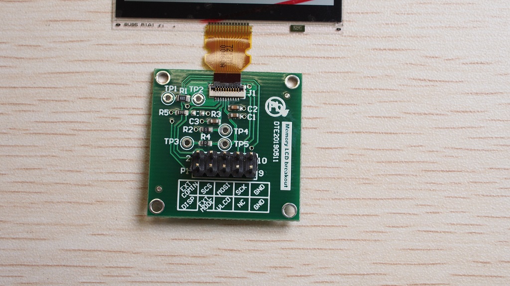
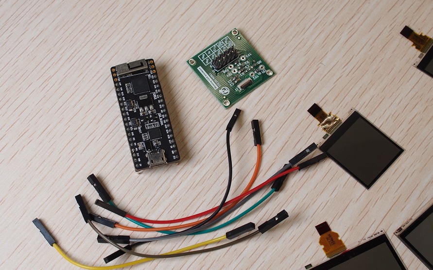
Driver compatible with ESP32 and Arduino M0 PRO listed in this repository. Although this driver has been developed for a dedicated EVK, a simplified breakout board with few jumper wires are enough to test this library out.
\MemoryLCD
	\picts
	\examples
		\BloodPressure_GUI
		\Energy
		\FirstPixel
		\HelloWorld
		\HelloWorld2
	\src
	library.properties
	README.md (this file)
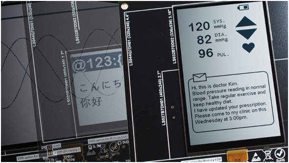
Install this library to /arduino libraries folder. In Arduino IDE from File->Examples->Custom Libraries you will see 5 examples. We have tested 5 Memory LCD models up to time of writing:
- LS027B7DH01 (2.7")
- LS032B7DD02 (3.2")
- LS044Q7DH01(4.4")
- LS006B7DH03 (0.56")
- LS011B7DH03 (1.08")
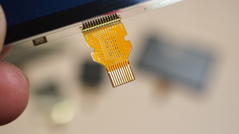
Different LCD sizes with the same FPC interface simplifies hardware design.
Selection options for which LCD model to use is available inMemoryLCD.h. Listing below shows an example with 2.7" model to use by leaving only#define LS027B7DH01while other models has been comment out.
#define   LS027B7DH01
//#define	LS032B7DD02
//#define 	LS044Q7DH01
//#define 	LS006B7DH03
//#define 	LS011B7DH03
With this breakout board there are only few jumper cables required to finish the setup. Photos of ESP32 PICO Kit and Arduino M0 PRO as examples:
Memory LCD is driven with two data update modes: 1-line mode and multiple-lines mode. There is no single pixel write! To get around this problem a frame buffer is declared to store all pixels in a 2D array:
uint8_t frameBuffer[GFX_FB_CANVAS_H][GFX_FB_CANVAS_W]
Each byte in the second subscript frameBuffer[0][x] represents 8 pixels in the horizontal direction. On the first horizontal line, pixels 0-7 are represented by frameBuffer[0][0], pixels 8-15 by frameBuffer[0][1] and so forth. Bitwise operation is used to fill up this frame buffer in SRAM of the MCU. After the required pixels have been updated in SRAM, the LCD is refreshed for a complete horizontal line with consecutive SPI transfers.
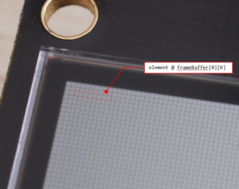
To illustrate this idea better we have captured the pixels on a 4.4" Memory LCD with a macro lens as below. The red rectangle is a label for the first 8 pixels represented by the byte element at framebuffer[0][0].
Now suppose we need to set the odd pixels to black color for positions 1,3,5,7 we may call the API function GFXDisplayPutPixel(x,y,color) with code snippet:
for (int x=0; x<8; x++)
{
	if(x%2)
		GFXDisplayPutPixel(x,0,WHITE);
	else
		GFXDisplayPutPixel(x,0,BLACK);
}
What's happening in the for-loop is that, every time GFXDisplayPutPixel() is called for example GFXDisplayPutPixel(0,0,BLACK), it is the pixel position at (0,0) set BLACK with framebuffer[0][0]=0b1111 1111 -> framebuffer[0][0]=0b0111 1111. A pixel is set white with bit set 1 & clear to 0 to set black. After bitwise is finished with GFXDisplayPutPixel_FB()the line will be updated by the local function GFXDisplayUpdateLine(). Interested readers may take a look at the source code for GFXDisplayPutPixel() here:
void GFXDisplayPutPixel(uint16_t x, uint16_t y, COLOR color)
{
	GFXDisplayPutPixel_FB(x, y, color);	//where bitwise operation in framebuffer occurs
	GFXDisplayUpdateLine(y+1, (uint8_t *)&frameBuffer[y]);	//update the line with SPI write
}
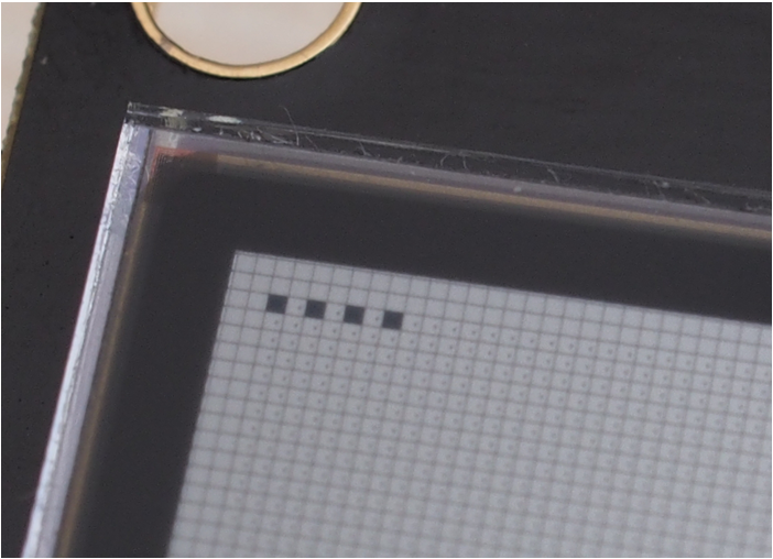
After running the for-loop above the LCD displays something this:
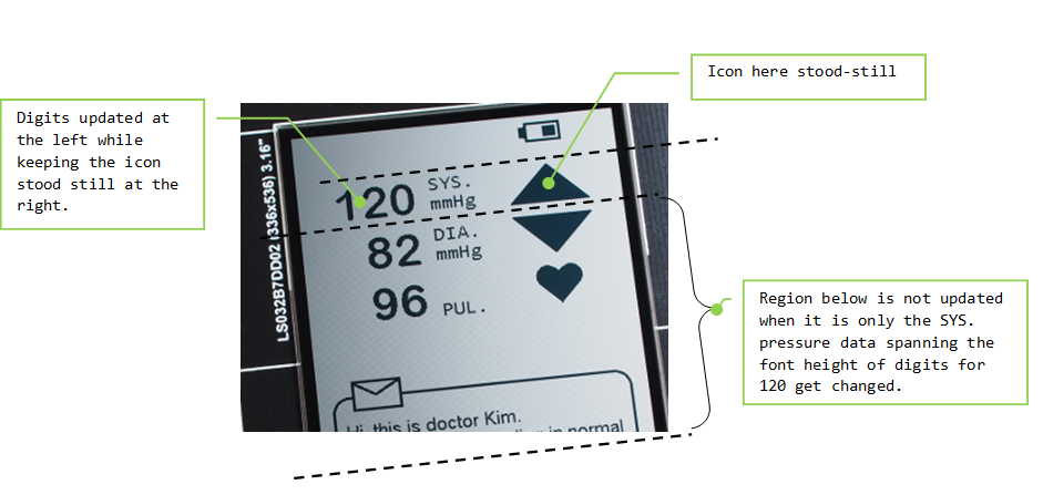
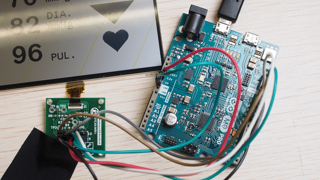
To extend this concept to 2D, we may partially update a rectangular area with GFXDisplayUpdateBlock() to keep the content at the right unchanged while updating the area at the left. Graphical interface illustrated in the Arduino Sketch BloodPressure_GU.ino shows a counting blood pressure reading at the left with a stood still icon of an up-arrow at the right. Feel free to open this sketch and change the delay constant in loop() from delay(50) to delay(1), or removing it to get an impression on how fast it can go. Another unique features of Memory LCD is partial update as long as it spans a horizontal region. Given the blood pressure reading GUI below this means only the area occupying the font height of the SYS. pressure is changed while the top and bottom regions unchanged when it is the systolic pressure counting.
This leads to a faster frame rate even with a slow SPI transfer rate of 2MHz.