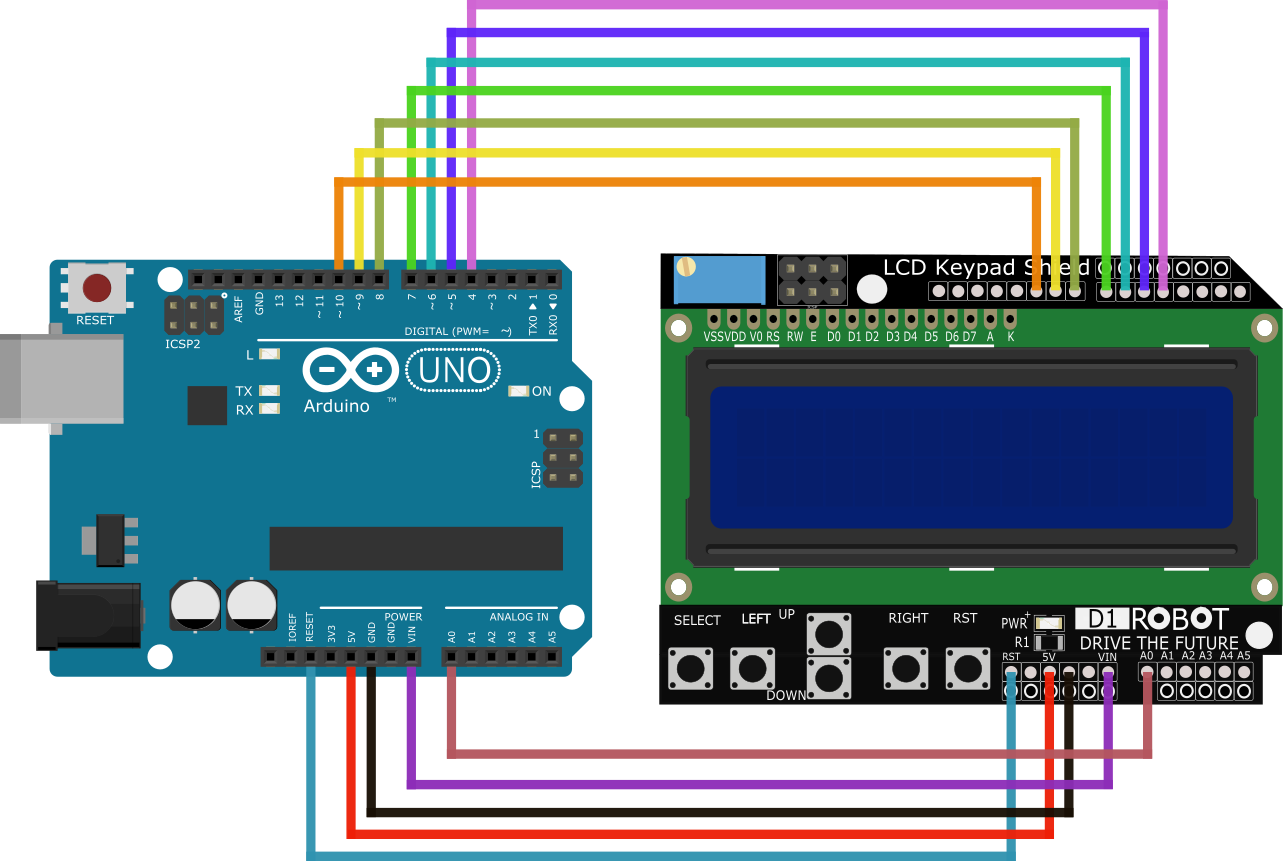
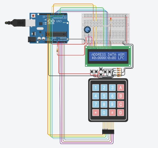
CMK computer is a bundle of arduino nano/uno, 16x2 LCD shield and 4x4 keypad
8-bit CPU emulator and a hex editor are flashed into ATMega328 microcontroller
Programs can be entered via machine codes from the keypad or loaded via serial port

- 1024 bytes of RAM (0x0000 - 0x03FF)
- 1024 bytes of EEPROM (bytes can be transfered between RAM and EEPROM)
- STACK starts at 0x03FF, growth downwards and does not wrap around
LCD shield   'left'    address mode
LCD shield  'right'    data mode
LCD shield     'up'    increase address by one
LCD shield   'down'    decrease address by one
LCD shield 'select'    switch keypad mode (DIGIT/COMMAND)
LCD shield  'reset'    hardware reset
Pressing a key on the keypad would result in
altering address/data (depending on mode) if
keypad is in the DIGIT mode and runs certain
commands in COMMAND mode.

|------------------------------------------------------|
| Button #  |              Command mode                |
|------------------------------------------------------|
| KEYPAD 1  | Copy 1024 bytes from EEPROM to RAM       |
| KEYPAD 3  | Copy 1024 bytes from RAM to EEPROM       |
| KEYPAD A  | Load bytes into RAM from serial port     |
| KEYPAD B  | Save bytes from RAM into serial port     |
|------------------------------------------------------|
| KEYPAD 2  | Increment ADDRESS/DATA depending on mode |
| KEYPAD 8  | Decrement ADDRESS/DATA depending on mode |
| KEYPAD 4  | Switch to ADDRESS mode                   |
| KEYPAD 6  | Switch to DATA mode                      |
|------------------------------------------------------|
| KEYPAD 5  | Switch between OPCODE/CHARACTER modes    |
|------------------------------------------------------|
| KEYPAD C  | Set current ADDRESS to Program counter   |
| KEYPAD D  | Print DEBUG info                         |
| KEYPAD E  | Execute a single instruction             |
| KEYPAD F  | Execute/Pause program                    |
|------------------------------------------------------|
| KEYPAD 0  | Reset RAM and CPU registers              |
|------------------------------------------------------|
| KEYPAD 7  | Not used in command mode                 |
| KEYPAD 9  | Not used in command mode                 |
|------------------------------------------------------|

F key is used to pause the program execution
during runtime regardless of modes. Please
do not involve it withing your programs.
----------------------------------------------------------
 HEX  ASM  ARG   Description
----------------------------------------------------------
0x00  NOP        no operation, resets program counter
0x01  LDI  byte  load immediate data to A register
0x02  LDA  word  load data from memory address with register B offset to A register
0x03  TAB        transfer data from A to B register
0x04  ADD  byte  add immediate data to A register and store it
0x05  SUB  byte  subtract immediate data from A register and store it
0x06  STA  word  set value from A register at memory address with register B offset
0x07  RCH        read character from keypad (non-blocking)
0x08  LPC  word  load data from memory address to program counter
0x09  INC        increment value in register B
0x0a  DCR        decrement value in register B
0x0b  CMP  byte  compare register A and immediate value, set zero flag
0x0c  JMP  word  jump program counter to memory address if zero flag is true
0x0d  DBG        print debug info to serial port
----------------------------------------------------------
0x0e  IN         get user input from keypad to A register (blocking)
0x0f  OUT        output character from A register to LCD
----------------------------------------------------------
0x10  BIT  byte  bitwise AND register A with immediate data, set zero flag
0x11  AND  byte  bitwise AND register A with immediate data, store result to A register
0x12  OR   byte  bitwise OR register A with immediate data, store result to A register
0x13  XOR  byte  bitwise XOR register A with immediate data, store result to A register
0x14  NOT  byte  bitwise NOT immediate data, store result to A register
0x15  SHL  byte  bitwise shift left register A with immediate data
0x16  SHR  byte  bitwise shift right register A with immediate data
----------------------------------------------------------
0x17  CLS        clear LCD display
0x18  SDL        Scrolls the contents of the display one space to the left
0x19  SDR        Scrolls the contents of the display one space to the right
0x1a  CRS        enable cursor (blink)
0x1b  NCR        disable cursor (no blink)
0x1c  UDG        create user defined character (assumes: A equals character id (0-7), B points to byte array)
0x1d  SPR  byte  draw sprite (0-7)
0x1e  POS        set cursor at position (assumes: A equals to column, B equals to row)
----------------------------------------------------------
0x1f  DLY  byte  delay execution
0x20  RND  byte  load random number between 0 and immediate date into A register
----------------------------------------------------------
0x21  PSH        push register A, then register B to stack
0x22  POP        pop register B, then register A from stack
0x23  SBR  word  call subroutine at memory address
0x24  RET        return from subroutine
----------------------------------------------------------
0x25  NUM  word  print (A!=0 DEC, A==0 HEX) number with (B==trailing 0) at memory address
0x26  INM  word  increment value at memory address
0x27  DCM  word  decrement value at memory address
----------------------------------------------------------
0x28  SER        output character from A register to serial port
start:         ; program start
  ldi 0x00     ; load 0 to A register
  tab          ; transfer the 0 from A to B register

print:         ; print string loop
  lda hello    ; load byte at 'hello' label address + B register offset
  cmp 0x00     ; zero terminating character?
  jmp exit     ; if so then exit the program
  dly 0xff     ; wait for 255 ms
  out          ; print character to LCD display
  inc          ; increment B reister by 1
  lpc print    ; jump to 'print' label

hello:         ; 'Hello, world!' string
  byte 0x48    ; 'H'
  byte 0x65    ; 'e'
  byte 0x6c    ; 'l'
  byte 0x6c    ; 'l'
  byte 0x6f    ; 'o'
  byte 0x2c    ; ','
  byte 0x20    ; ' '
  byte 0x77    ; 'w'
  byte 0x6f    ; 'o'
  byte 0x72    ; 'r'
  byte 0x6c    ; 'l'
  byte 0x64    ; 'd'
  byte 0x21    ; '!'

hello_end:     ; prorgam end
  byte 0x00    ; zero terminating character

exit:          ; clean ups before exit
  ldi 0x02     ; load 2 to A register
  tab          ; transfer to from A to B register
  ldi 0x00     ; load 0 to A register
  pos          ; position cursor at A, B (col 0, row 2)
  byte 0x00    ; execution terminates here
python3 assembler.py hello.asm