This article describes some analysis performed on a defective Aerocool fan. Model is WX-14025 (14 cm), "Made in China" with a sticker indicating 12V-DC 0.25A on the back.
The fan was part of a Trinity White Tower V3 made by Aerocool and shipped with two front fans of 14 cm and one back fan of 12 cm, all of them with a flashy RGB effect out of the box. After only a few startups, the lower front fan was displaying a steady white color in one corner. The rest of the fans were not illuminated (hue in the upper fan in the picture is coming from some backlights).

After verifying all cables and trying several times to reconnect the SATA power, I came to the conclusion that some electronical issue was present and somehow explain the low cost of the whole unit. Each fan has four wires. The first fan has a special connector such that the daisy-chained set of fans can be powered by a single SATA power cable. The last wire, which is not wired to the SATA power connector, is clearly dedicated to some data line and this data line is shared across all the fans.
By default, the RGB effect on these fans is some kind of rotating rainbow. As no other device is attached to the fans (no hub or controller), something in one of the fan must be generating a signal that was used to drive the led stripes. Moreover the same exact effect was present in all fans before they failed and they were perfectly synchronized before the failure (see picture below) confirming that the 4th wire was actually used to share the same data across all fans. No information about the protocol being used on the data line is available and the documentation of Aerocool was not helpful to figure out anything regarding the pinouts.

As I had little faith in being able to fix the problem - I was first suspecting a nasty microscopic shortcut in one of these wires - I decided to unmount all fans, order another set of hopefully better fans from a different manufacturer (Be Quiet) meanwhile and try to understand how this thing was supposed to work.
I first focused my attention on the fan that looked to be defective and had some white leds that kept being on. This is also the only fan that has another set of wires going to a two pins connector which is supposed to be connected to the reset switch of the case (to change color modes) - note that the "manual" shipped with the case did not mention this... There are several wires arriving on the small PCB that is behind the motor.
From top to bottom on the picture:
- 12V
- -12V, wrongly marked as it's GND
- GND, yellow wire
- White
- +5V, black wire at bottom
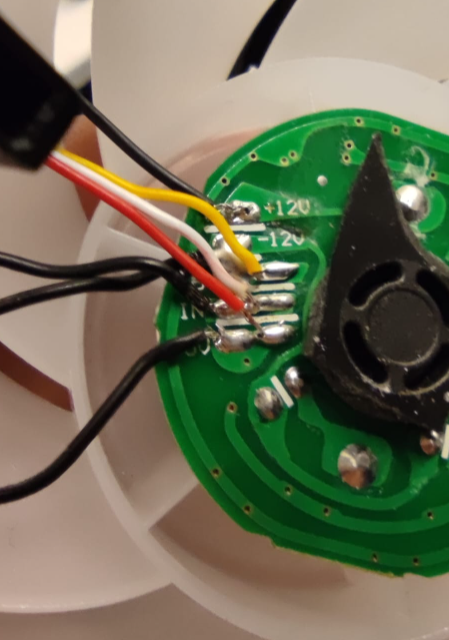
This pattern confirms that the white must be some kind of serial line dedicated to color commands as the other wires are only for power.
Next I cut open the whiteish circle band that covers the outer leds strip, near the point where the yellow/white/black wire are arriving from the central PCB. Two sections are visible.
The first one is dedicated to the "color mode".
- GND --> going to reset switch
- Key --> going to reset switch
The 2nd part
- TB, purpose is unknown. Maybe for testing
- GND (yellow)
- IN (white), corresponds to the serial data line
- +5V (red)

Next to these connections, I discovered a small IC with a very suspicious black spot on top. Scratching it with the finger nail leaves some charcoal residue, it is definitely burnt. Now I get a full picture of the failure and concludes that this IC is the brain and is directly commanding the data line. As this data line is then shared with other fans, it can send the same signal to all fans that are connected to the main one (and thus have colors in sync).
This IC was either defect, got shorted or subject to some current spikes and failed after a few startups.

As I was mainly interested into the color strips, I left the +12V line aside to focus on the GND/Data/5V part. As everything is driven by a single data line, I made the hypothesis that the manufacturer probably had used a common and cheap solution present in many RGB lights and strips: the WS2812B serial protocol.
I will not go into details about WS2812B itself but the idea is basically to send a stream of bits along the data line with one packet per led. When a led receives the stream, it takes a given number of bits (that correspond to the colors), remove them from the rest of the stream and pass that result to the next led. And so on until no bits are left and all of them have been consumed by the leds. It could have been WS2813 but the main difference is that the WS2813 is resistant to the failure of one led in the middle of the strip. In the case of WS2812B, if one led is failing it will not transmit the rest of the stream and the communication will be broken. The WS2813 is slightly more expensive and I think they chose the cheapest solution considering the overall low cost of this case (under 65$).
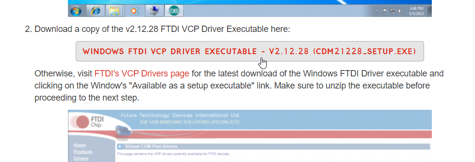
I grabbed my old Diecimila Arduino board that had not be used for something like 8 years and prepared a small test setup. I struggled a bit with the Arduino on my computer and the new IDE, the Diecimila is using an ATMEGA 168 (you must explicitely indicate that in the IDE configuration) but I still could not get it to work - the upload was failing. After some googling, I found out that you have to install some FTDI drivers (https://learn.sparkfun.com/tutorials/how-to-install-ftdi-drivers/all).
There are many tutorials about interfacing an Arduino with a WS2812b strip, I picked that one which is great and pretty complete, installed the FastLED library and picked the provided sketch without any modification: https://randomnerdtutorials.com/guide-for-ws2812b-addressable-rgb-led-strip-with-arduino/
It is usually wiser to use an external power supply as the leds are drawing a lot of current. I connected the +5V and GND of my power supply to the +5V and GND of the fan according to the reverse-engineered pinout. It was unclear whether it was a good idea to keep the USB connected - discussions are mixed regarding that point - so I only powered the board with the external supply after I had uploaded the sketch and deconnected the USB cable. The data line of the fan is connected to the pin 5 of the Arduino as described in the tutorial.
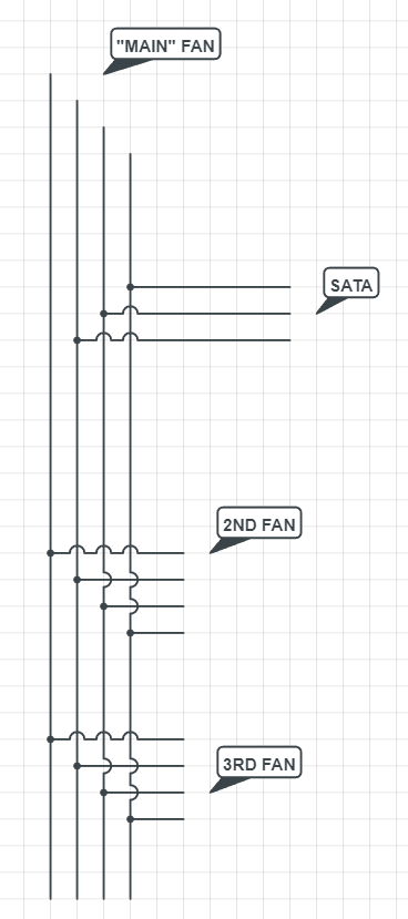
On the picture below, you will find the pin configuration on the connectors provided with the Aerocool fans. As said before, the 12V is not connected as I was not interested into making them rotate.

The fan immediately starts to display colorful patterns which are totally in line with the description of the palettes provided by the sketch in the tutorial. This was the confirmation they are using a plain WS2812b protocol and that you could reuse them for another application without particular tweaks.

Strip pattern from the tutorial - totally matches the one displayed on the fan:


