BeagleConnect™
BeagleConnect™ is a revolutionary technology virtually eliminating low-level software development for IoT and IIoT applications, such as building automation, factory automation, home automation, and scientific data acquisition. While numerous IoT and IIoT solutions available today provide massive software libraries for microcontrollers [1] supporting a limited body of sensors, actuators and indicators as well as libraries for communicating over various networks, BeagleConnect simply eliminates the need for these libraries by shifting the burden into the most massive and collaborative software project of all time, the Linux kernel.
These are the tools used to automate things in scientific data collection, data science, mechatronics, and IoT.
BeagleConnect™ technology solves:
-
The need to write software to add a large set of diverse devices to your system,
-
The need to maintain the software with security updates,
-
The need to rapidly prototype using off-the-shelf software and hardware without wiring,
-
The need to connect to devices using long-range, low-power wireless, and
-
The need to produce high-volume custom hardware cost-optimized for your requirements.
- BeagleConnect™ experience
- BeagleConnect™ hardware
- The Story Behind BeagleConnect™
- Architecture
- Usage
- Develop for BeagleConnect™ Freedom with Zephyr
- Equipment to begin development
- Install the latest software image for BeagleBone Green Gateway
- Log into BeagleBone Green Gateway
- Install Zephyr development tools on BeagleBone Green Gateway
- Build applications for BeagleConnect Freedom on BeagleBone Green Gateway
- Flash applications to BeagleConnect Freedom from BeagleBone Green Gateway
- Debug applications over the serial terminal
- Work in progress
- BeagleConnect™ Greybus demo using BeagleConnect™ Freedom
BeagleConnect™ experience
BeagleConnect™ provides a scalable experience for interacting with the physical world.
|
ℹ️
|
The term BeagleConnect™ refers to a technology comprising of a family of boards, a collection of Linux kernel drivers, microcontroller firmware, a communication protocol, and system-level integration to automation software tools. More specific terms will be applied in the architecture details. The term is also used here to represent the experience introduced to users through the initial BeagleConnect™ Freedom product consisting of a board and case which ships programmed and ready to be used. |
For scientists, we are integrating Jupyter Notebook with the data streams from any of hundreds of sensor options, including vibration, gas detection, biometrics and more. These data streams can be stored in simple data files or processed and visualized.
#TODO: provide images demonstrating Jupyter Notebook visualization
For embedded systems developers, data is easily extrated using the standard IIO interface provided by the Linux kernel running on the gateway using any of hundreds of programming languages and environments, without writing a line of microcontroller firmware. The Linux environment provides opportunities for high-level remote management using tools like Balena with applications deployed in Docker containers.
#TODO: provide image illustrating remote management
The hardware and software are fully open source, providing for scalability and a lack of vendor lock-in.
For DevOps…
For home automaters, integration into WebThings…
#TODO: think a bit more about this section with some feedback from Cathy.
BeagleConnect™ hardware
BeagleConnect™ Freedom
#TODO: provide image of BeagleConnect™ Freedom in case with a hand for size perspective
|
❗
|
BeagleConnect™ Freedom enables wirelessly adding new device nodes and is targeted to cost initially around US$20 with a roadmap to variants as low as US$1. |
The initial BeagleConnect™ Freedom production release will:
-
Support at least 100 mikroBUS-based Click boards from Mikroelectronika,
-
Work with Bluetooth Low Energy (BLE)-enabled Linux computers at 2.4GHz,
-
Work with long-range sub-1GHz IEEE 802.15.4 wireless connections at 500 meters with data rates of 1kbps, and
-
Work with a low-cost BeagleBoard.org Linux single-board computer (SBC) as a
BeagleConnect™ gateway deviceand work with at least 10 otherBeagleConnect™ node deviceseach supporting 2 add-on sensor, actuator or indicator devices.
Future releases will be collaborated with the community, evolve dynamically, and contain additional functionality. The goal is to support over 500 add-on devices within the first year after the initial release.
BeagleConnect™ Freedom beta kit
A small number of beta kits have been assembled with BeagleConnect™ Freedom rev C5 boards, which is the version that should be taken to production.
The kit includes:
-
1x Seeed BeagleBone® Green Gateway (board, USB cable)
-
3x BeagleConnect™ Freedom (board, attenna, USB cable)
To get started with this kit, see BeagleConnect™ Greybus demo using BeagleConnect™ Freedom.
BeagleConnect™ Mobile Gateway
This is a work-in-progress that will be released as the first integrated BeagleConnect™ gateway. It is possible to assemble a gateway with any Linux computer, but this computer will ship setup and ready to go.
The gateway is built from:
-
BeagleBoard.org PocketBeagle,
-
BeagleConnect™ Freedom,
-
a cellular modem,
-
a USB WiFi dongle,
-
antennas, and
-
an enclosure.
The Story Behind BeagleConnect™
The Long Background
There are many stories behind BeagleConnect™, mine is just one of them. It begins with my mom teaching me about computers. She told me I could anything I wanted with ours, as long as I didn’t open the case. This was the late-70s/early-80s, so all she needed to do was put her floppy disk away and there wasn’t risk of me damaging the family photo album or her ability to do her work the next day. I listened and learned from her the basics of programming, but it wasn’t long before I wanted to take the computer apart.
Getting Started in Electronics
Exploring Getting Started in Electronics satisfied my itch for quite a while. Eventually, I got a Commodore 64 and began connecting voice synthesizer ICs to it. My interest in computers and electronics flourished into an electrical engineering degree and a long career in the semiconductor industry.
Over this time, I’ve become more and more alarmed with the progress of technology. Now, to be clear, I love technology. I love innovation and invention. It is just that some things have evolved in a sort of tunnel-vision, without bringing everyone along.
But, what about keyboard users?
As graphical user interfaces and mice took over computers, they rapidly became almost unusable by my mom. She typed well, but the dexterity to move a mouse aluded her. To satisfy the need to interact with locations on the screen, she adopted using a joystick and her productivity came to a crawl. How is it that such assumptions could be made impacting all computer users without any thoughtful provisions for what already worked?
Find out more
Get on my calendar if you’d like to chat with me more about this story.
Architecture
BeagleConnect™ Freedom
BeagleConnect™ Freedom is based on the TI CC1352 and is the first available BeagleConnect™ solution. It implements:
-
BeagleConnect™ gateway devicefunction for Sub-GHz 802.15.4 long-range wireless -
BeagleConnect™ node devicefunction for Bluetooth Low-Energe (BLE) and Sub-GHz 802.15.4 long range wireless -
USB-based serial console and firmware updates
-
2x mikroBUS sockets with
BeagleConnect™ protocol support


What makes BeagleConnect™ new and different?
|
❗
|
BeagleConnect™ solves IoT in a different and better way than any previous solution. |
The device interface software is already done
BeagleConnect™ uses the collaboratively developed Linux kernel to contain the intelligence required to speak to these devices (sensors, actuators, and indicators), rather than relying on writing code on a microcontroller specific to these devices. Some existing solutions rely on large libraries of microcontroller code, but the integration of communications, maintenance of the library with a limited set of developer resources and other constraints to be explained later make those other solutions less suitable for rapid prototyping than BeagleConnect™.
Linux presents these devices abstractly in ways that are self-descriptive. Add an accelerometer to the system and you are automatically fed a stream of force values in standard units. Add a temperature sensor and you get it back in standard units again. Same for sensing magnetism, proximity, color, light, frequency, orientation, or multitudes of other inputs. Indicators, such as LEDs and displays, are similarly abstracted with a few other kernel subsystems and more advanced actuators with and without feedback control are in the process of being developed and standardized. In places where proper Linux kernel drivers exist, no new specialized code needs to be created for the devices.
|
❗
|
Bottom line: For hundreds of devices, users won’t have to write a single line of code to add them their systems. The automation code they do write can be extremely simple, done with graphical tools or in any language they want. Maintenance of the code is centralized in a small reusable set of microcontroller firmware and the Linux kernel, which is highly peer reviewed under a highly-regarded governance model. |
On-going maintenance
Because there isn’t code specific to any given network-of-devices configuration, we can all leverage the same software code base. This means that when someone fixes an issue in either BeagleConnect™ firmware or the Linux kernel, you benefit from the fixes. The source for BeagleConnect™ firmware is also submitted to the Zephyr Project upstream, further increasing the user base. Additionally, we will maintain stable branches of the software and provide mechanisms for updating firmware on BeagleConnect™ hardware. With a single, relatively small firmware load, the potential for bugs is kept low. With large user base, the potential for discovering and resolving bugs is high.
Rapid prototyping without wiring
BeagleConnect™ utilizes the mikroBUS standard. The mikroBUS standard interface is flexible enough for almost any typical sensor or indicator with hundreds of devices available.
|
ℹ️
|
Currently, we have support in the Linux kernel for a bit over 100 Click mikroBUS add-on boards from Mikroelektronika and are working with Mikroelektronika on a updated version of the specification for these boards to self-identify. Further, eventually the vast majority of over 800 currently available Click mikroBUS add-on boards will be supported as well as the hundreds of compliant boards developed every year. |
Long-range, low-power wireless
BeagleConnect™ Freedom wireless hardware is built around a TI CC1352 multiprotocol and multi-band Sub-1 GHz and 2.4-GHz wireless microcontroller (MCU). CC1352R includes a 48-MHz Arm® Cortex®-M4F processor, 352KB Flash, 256KB ROM, 8KB Cache SRAM, 80KB of ultra-low leakage SRAM, and Over-the-Air upgrades (OTA).
Full customization possible
BeagleConnect™ utilizes open source hardware and open source software, making it possible to optimize hardware and software implementations and sourcing to meet end-product requirements. BeagleConnect™ is meant to enable rapid-prototyping and not to necessarily satisfy any particular end-product’s requirements, but with full considerations for go-to-market needs.
Each BeagleBoard.org BeagleConnect™ solution will be:
-
Readily available for over 10 years,
-
Built with fully open source software with submissions to mainline Linux and Zephyr repositories to aide in support and porting,
-
Built with fully open source and non-restrictive hardware design including schematic, bill-of-materials, layout, and manufacturing files (with only the BeagleBoard.org logo removed due to licensing restrictions of our brand),
-
Built with parts where at least a compatible part is available from worldwide distributors in any quantity,
-
Built with design and manufacturing partners able to help scale derivative designs,
-
Based on a security model using public/private keypairs that can be replaced to secure your own network, and
-
Fully FCC/CE certified.
Usage
This section describes the usage model we are developing. To use the current code in development, please refer to the Develop for BeagleConnect™ Freedom with Zephyr section below.
BeagleConnect™ wireless user experience
Enable a Linux host with BeagleConnect™
 Log into a host system running Linux that is BeagleConnect™
enabled. Enable a Linux host with BeagleConnect™ by plugging a
Log into a host system running Linux that is BeagleConnect™
enabled. Enable a Linux host with BeagleConnect™ by plugging a
BeagleConnect™ gateway device into it’s USB port. You’ll also want to have a
BeagleConnect™ node device with a sensor, actuator or indicator device connected.
|
ℹ️
|
BeagleConnect™ Freedom can act as either a BeagleConnect™ gateway device or a
BeagleConnect™ node device.
|
|
❗
|
The Linux host will need to run the BeagleConnect™ management
software, most of which is incorporated into the Linux kernel. Support will
be provided for BeagleBoard and BeagleBone boards, x86 hosts, and Raspberry Pi.
|
TODO: Clean up images
Connect host and device
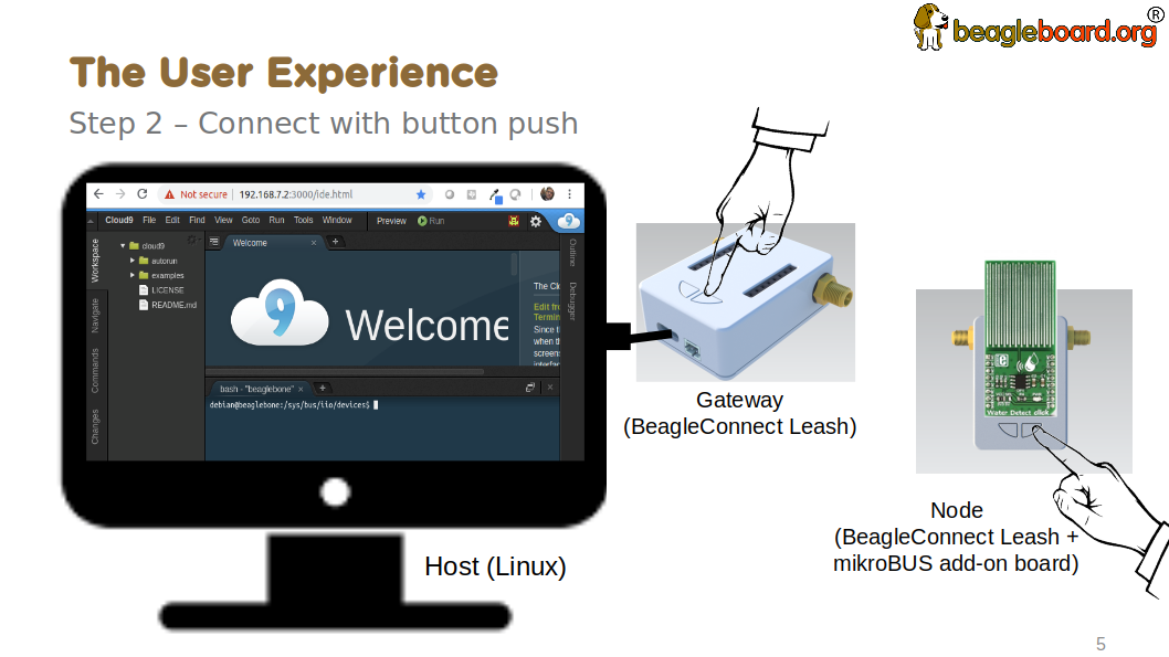 Initiate a connection between the host and devices by pressing
the discovery button(s).
Initiate a connection between the host and devices by pressing
the discovery button(s).
Device data shows up as files
 New streams of self-describing data show up on the host system
using native device drivers.
New streams of self-describing data show up on the host system
using native device drivers.
High-level applications, like Node-RED, can directly read/write these high-level
data streams (including data-type information) to Internet-based MQTT brokers,
live dashboards, or other logical operations without requiring any sensor-specific
coding. Business logic can be applied using simple if-this-then-that style operations
or be made as complex as desired using virtually any programming language or environment.
TODO: Actually, Node-RED will make these show up automatically as streams.
Components
| BeagleConnect™ enabled host |
Linux computer, possibly single-board computer (SBC), with
|
||
| BeagleConnect™ Freedom |
Board, case, and wireless MCU with
|
||
| BeagleConnect™ gateway device |
Provides a |
||
| BeagleConnect™ node device |
Utilizes a |
||
| BeagleConnect™ compatible interface |
Immediate plans are to support Bluetooth Low Energy (BLE),
2.4GHz IEEE 802.15.4, and Sub-GHz IEEE 802.15.4 wireless interfaces. A built-in BLE interface is
suitable for this at short range, whereas IEEE 802.15.4 is typically significantly better at long
ranges. Other wired interfaces, such as CAN and RS-485, are being considered for future
|
||
| Greybus |
TODO |
#TODO: Find a place for the following notes:
-
The device interfaces get exposed to the host via Greybus BRIDGED_PHY protocol
-
The I2C bus is probed for a an identifier EEPROM and appropriate device drivers are loaded on the host
-
Unsupported Click Boards connected are exposed via userspace drivers on the host for development
What’s different
So, in summary, what is so different with this approach?
-
No microcontroller code development is required by users
-
Userspace drivers make rapid prototyping really easy
-
Kernel drivers makes the support code collaborative parts of the Linux kernel, rather than cut-and-paste
Develop for BeagleConnect™ Freedom with Zephyr
Developing directly in Zephyr will not be ultimately required for end-users who won’t touch the firmware running on BeagleConnect™ Freedom and will instead use the BeagleConnect™ Greybus functionality, but is important for early adopters as well as people looking to extend the functionality of the open source design. If you are one of those people, this is a good place to get started.
Equipment to begin development
There are many options, but let’s get started with one recommended set for the beta users.
Required
-
BeagleConnect™ Freedom beta kit
-
3x BeagleConnect™ Freedom board, antenna, U.FL to SMA cable, SMA antenna and USB Type-A to Type-C cable
-
1x MikroE ID Click
-
microSD card (6GB or larger)
-
microSD card programmer
Recommended
-
Ethernet cable and Internet connection
-
2x USB power adapters
Optional
-
x86_64 computer running Ubuntu 20.04.3 LTS
Install the latest software image for BeagleBone Green Gateway
Download and install the Debian Linux operating system image for the Seeed BeagleBone® Green Gateway host.
-
Download the special mikroBUS/Greybus BeagleBoard.org Debian image from here. Pick the most recent directory and select the file beginning with bone- and ending with .img.xz. Today that file is bone-debian-11.2-iot-mikrobus-armhf-2022-03-04-4gb.img.xz.
-
Load this image to a microSD card using a tool like Etcher.
-
Insert the microSD card into the Green Gateway.
-
Power BeagleBone Green Gateway via the 12V barrel jack.
#TODO: describe how to know it is working
Log into BeagleBone Green Gateway
These instructions assume an x86_64 computer runing Ubuntu 20.04.3 LTS, but any computer can be used to connect to your BeagleBone Green Gateway.
-
Log onto the Seeed BeagleBone® Green Gateway using
sshor, with a serial to USB cable such as those made by FTDI plugged into J10 with the black wire of the FTDI cable toward the Ethernet connector. To usessh, you will have to know the Green Gateway’s IP address that can be found from your router. -
(If using WiFi) Use the
connmanctltool to gain an Internet connection.
#TODO: Simplify and elaborate on this section
Install Zephyr development tools on BeagleBone Green Gateway
sudo apt update
sudo apt install -y \
	beagleconnect beagleconnect-msp430 \
	git vim \
	build-essential \
	cmake ninja-build gperf \
	ccache dfu-util device-tree-compiler \
	make gcc libsdl2-dev \
	libxml2-dev libxslt-dev libssl-dev libjpeg62-turbo-dev \
	gcc-arm-none-eabi libnewlib-arm-none-eabi \
	libtool-bin pkg-config autoconf automake libusb-1.0-0-dev \
	python3-dev python3-pip python3-setuptools python3-tk python3-wheel
pip3 install -U west
echo "export PATH=$PATH:$HOME/.local/bin" >> $HOME/.bashrc
source $HOME/.bashrc
cd
west init -m https://github.com/jadonk/zephyr --mr bcf-sdk-0.0.5 bcf-zephyr
cd $HOME/bcf-zephyr
west update
west zephyr-export
pip3 install -r zephyr/scripts/requirements-base.txt
echo "export CROSS_COMPILE=/usr/bin/arm-none-eabi-" >> $HOME/.bashrc
echo "export ZEPHYR_BASE=$HOME/bcf-zephyr/zephyr" >> $HOME/.bashrc
echo "export PATH=$HOME/bcf-zephyr/zephyr/scripts:$PATH" >> $HOME/.bashrc
echo "export BOARD=beagleconnect_freedom" >> $HOME/.bashrc
source $HOME/.bashrc
Build applications for BeagleConnect Freedom on BeagleBone Green Gateway
Now you can build various Zephyr applications
cd $HOME/bcf-zephyr
west build -d build/blinky zephyr/samples/basic/blinky
west build -d build/sensortest zephyr/samples/boards/beagle_bcf/sensortest -- -DOVERLAY_CONFIG=overlay-subghz.conf
west build -d build/wpanusb modules/lib/wpanusb_bc -- -DOVERLAY_CONFIG=overlay-subghz.conf
west build -d build/bcfserial modules/lib/wpanusb_bc -- -DOVERLAY_CONFIG=overlay-bcfserial.conf -DDTC_OVERLAY_FILE=bcfserial.overlay
west build -d build/greybus modules/lib/greybus/samples/subsys/greybus/net -- -DOVERLAY_CONFIG=overlay-802154-subg.conf
Flash applications to BeagleConnect Freedom from BeagleBone Green Gateway
And then you can flash the BeagleConnect Freedom boards over USB
cd $HOME/bcf-zephyr
cc2538-bsl.py build/blinky
Debug applications over the serial terminal
#TODO
Work in progress
To understand a bit more about how the BeagleConnect™ Greybus stack is being built, this section helps describe the development currently in progress and the principles of operation.
Background
 BeagleConnect™ uses Greybus and updated Click Boards with
identifiers to eliminate the need to add and manually configure devices
added onto the Linux system.
BeagleConnect™ uses Greybus and updated Click Boards with
identifiers to eliminate the need to add and manually configure devices
added onto the Linux system.
High-level
-
For Linux nerds: Think of BeagleConnect™ as 6LoWPAN over 802.15.4-based Greybus (instead of Unipro as used by Project Ara), where every BeagleConnect™ board shows up as new SPI, I2C, UART, PWM, ADC, and GPIO controllers that can now be probed to load drivers for the sensors or whatever is connected to them. (Proof of concept of Greybus over TCP/IP: https://www.youtube.com/watch?v=7H50pv-4YXw)
-
For MCU folks: Think of BeagleConnect™ as a Firmata-style firmware load that exposes the interfaces for remote access over a secured wireless network. However, instead of using host software that knows how to speak the Firmata protocol, the Linux kernel speaks the slightly similar Greybus protocol to the MCU and exposes the device generically to users using a Linux kernel driver. Further, the Greybus protocol is spoken over 6LoWPAN on 802.15.4.
Software architecture

TODO items
-
Linux kernel driver
-
Provisioning
-
Firmware for host CC13x
-
Firmware for device CC13x
-
Click Board drivers and device tree formatted metadata for 100 or so Click Boards
-
Click Board plug-ins for node-red for the same 100 or so Click Boards
-
BeagleConnect™ Freedom System Reference Manual and FAQs
Associated pre-work
-
Click Board support for Node-RED can be executed with native connections on PocketBeagle+TechLab and BeagleBone Black with mikroBUS Cape
-
Device tree fragments and driver updates can be provided via https://bbb.io/click
-
The Kconfig style provisioning can be implemented for those solutions, which will require a reboot. We need to centralize edits to /boot/uEnv.txt to be programmatic. As I think through this, I don’t think BeagleConnect is impacted, because the Greybus-style discovery along with Click EEPROMS will eliminate any need to edit /boot/uEnv.txt.
User experience concerns
-
Make sure no reboots are required
-
Plugging BeagleConnect into host should trigger host configuration
-
Click EEPROMs should trigger loading whatever drivers are needed and provisioning should load any new drivers
-
Userspace (spidev, etc.) drivers should unload cleanly when 2nd phase provisioning is completed
BeagleConnect™ Greybus demo using BeagleConnect™ Freedom
BeagleConnect™ Freedom runs a subGHz IEEE 802.15.4 network. This BeagleConnect™ Greybus demo shows how to interact with GPIO, I2C and mikroBUS add-on boards remotely connected over a BeagleConnect™ Freedom.
This section starts with the steps required to use Linux embedded computer (BeagleBone Green Gateway) and the Greybus protocol, over an IEEE 802.15.4 wireless link, to blink an LED on a Zephyr device.
Introduction
Why??
Good question. Blinking an LED is kind of the Hello, World of the hardware community. In this case, we’re less interested in the mechanics of switching a GPIO to drive some current through an LED and more interested in how that happens with the Internet of Things (IoT).
There are several existing network and application layers that are driven by corporate heavyweights and industry consortiums, but relatively few that are community driven and, more specifically, even fewer that have the ability to integrate so tightly with the Linux kernel.
The goal here is to provide a community-maintained, developer-friendly, and open-source protocol for the Internet of Things using the Greybus Protocol, and blinking an LED using Greybus is the simplest proof-of-concept for that. All that is required is a reliable transport.
History
There are a few technologies at the core of this demonstration, and far too much background information to describe adequately here, so they are simply listed below for brevity:
-
Zephyr support for IEEE 802.15.4
-
Greybus originally from Project Ara
In short, Greybus is an application layer protocol that can be described as a ``bus transport'' in that it conveys bus-specific messages back and forth between Linux and a connected device. The physical bus is attached to the connected device, which could be running Linux or a variety of Real-Time Operating Systems. Meanwhile, on the Linux side, a virtual bus is created corresponding to the physical bus on the connected device. To the user, this virtual bus (be it /dev/gpiochip0, /dev/i2c5, etc) appears and functions exactly the same. Greybus is the protocol used to exchange bus-specific messages and data between Linux and the connected device.
The major advantage there is that drivers can be well maintained in Linux rather than buried in microcontroller firmware.
Greybus currently supports several busses, including:
-
USB
-
I2C
-
GPIO
-
PWM
-
SPI
-
UART
-
SDIO
-
Camera (V4L)
-
LED (with various programmability)
-
AUDIO (I2S)
#TODO: The agenda for the above falls a bit short of BeagleConnect
Hardware requirements
See the [Equipment] section for hardware requirements.
Running the demo
#TODO: Fill in some details for new embedded Linux users
#TODO: Arrange demo in order of fast success to greater understanding
Install the latest software image
Download and install the Debian Linux operating system image for the Seeed BeagleBone® Green Gateway host.
-
Download the special mikroBUS/Greybus BeagleBoard.org Debian image from here. Pick the most recent directory and select the file beginning with bone- and ending with .img.xz. Today that file is bone-debian-11.2-iot-mikrobus-armhf-2022-03-04-4gb.img.xz.
-
Load this image to a microSD card using a tool like Etcher.
-
Insert the microSD card into the Green Gateway.
-
Power the Green Gateway via the 12V barrel jack.
-
Log onto the Seeed BeagleBone® Green Gateway using
sshor, with a serial to USB cable such as those made by FTDI[https://www.digikey.com/short/cfjmdbdd] plugged into J10 with the black wire of the FTDI cable toard the Ethernet connector. To usessh, you will have to know the Green Gateway’s IP address that can be found from your router. -
(If using WiFi) Use the
connmanctltool to gain an Internet connection.
Flash BeagleConnect™ Freedom gateway device
Comamnd-line instructions below are to be issued into the BeagleBone® Green Gateway terminal, either via ssh or the serial console.
On the newly imaged BeagleBone® Green Gateway board:
-
Connect (or reconnect) a BeagleConnect™ Freedom board over USB
-
cc2538-bsl.py /usr/share/beagleconnect/cc1352/wpanusb_beagleconnect.bin /dev/ttyACM0[2] -
After it finishes programming successfully, reconnect the BeagleConnect Freedom board over USB
-
Test that the driver loaded and is talking to the newly added gateway radio
debian@beaglebone:~$ iwpan wpan0 info
Interface wpan0
        ifindex 10
        wpan_dev 0x200000001
        extended_addr 0x5a4f745eb7beac7f
        short_addr 0xffff
        pan_id 0xffff
        type node
        max_frame_retries 3
        min_be 3
        max_be 5
        max_csma_backoffs 4
        lbt 0
        ackreq_default 0
Test gateway using pre-programmed node firmware
By default, the beta boards ship with a debug sensor broadcast per sensortest-main.c. You can use this to further test your gateway.
-
Power a BeagleConnect Freedom that has not yet been programmed via a USB power source, not the BeagleBone Green Gateway. You’ll hear a click every 1-2 seconds along with seeing 4 of the LEDs turn off and on.
-
In an isolated terminal window,
sudo beagleconnect-start-gateway -
sensortest-rx.py
Every 1-2 minutes, you should see something like:
('fe80::3111:7a22:4b:1200%lowpan0', 52213, 0, 13)  '2l:7.79;'
('fe80::3111:7a22:4b:1200%lowpan0', 52213, 0, 13)  '4h:43.75;4t:23.11;'
The value after "2l:" is the amount of light in lux. The value after "4h:" is the relative humidity and after "4t:" is the temperature in Celcius.
Flash BeagleConnect™ Freedom node device with Greybus firmware
#TODO: How can we add a step in here to show the network is connected without needing gbridge to be fully functional?
Do this from the BeagleBone® Green Gateway board that was previously used to program the BeagleConnect™ Freedom gateway device:
-
Disconnect the BeagleConnect™ Freedom gateway device
-
Connect a new BeagleConnect™ Freedom board via USB
-
sudo systemctl stop lowpan.service -
cc2538-bsl.py /usr/share/beagleconnect/cc1352/greybus_mikrobus_beagleconnect.bin /dev/ttyACM0[3] -
After it finishes programming successfully, disconnect the BeagleConnect Freedom node device
-
Power the newly programmed BeagleConnect Freedom node device from an alternate USB power source
-
Reconnect the BeagleConnect Freedom gateway device to the BeagleBone Green Gateway
-
sudo systemctl start lowpan.service -
sudo beagleconnect-start-gateway
debian@beaglebone:~$ sudo beagleconnect-start-gateway
[sudo] password for debian:
setting up wpanusb gateway for IEEE 802154 CHANNEL 1(906 Mhz)
ping6: Warning: source address might be selected on device other than lowpan0.
PING 2001:db8::1(2001:db8::1) from ::1 lowpan0: 56 data bytes
64 bytes from 2001:db8::1: icmp_seq=2 ttl=64 time=185 ms
64 bytes from 2001:db8::1: icmp_seq=3 ttl=64 time=40.9 ms
64 bytes from 2001:db8::1: icmp_seq=4 ttl=64 time=40.9 ms
64 bytes from 2001:db8::1: icmp_seq=5 ttl=64 time=40.6 ms

--- 2001:db8::1 ping statistics ---
5 packets transmitted, 4 received, 20% packet loss, time 36ms
rtt min/avg/max/mdev = 40.593/76.796/184.799/62.356 ms
debian@beaglebone:~$ iio_info
Library version: 0.19 (git tag: v0.19)
Compiled with backends: local xml ip usb serial
IIO context created with local backend.
Backend version: 0.19 (git tag: v0.19)
Backend description string: Linux beaglebone 5.14.18-bone20 #1buster PREEMPT Tue Nov 16 20:47:19 UTC 2021 armv7l
IIO context has 1 attributes:
	local,kernel: 5.14.18-bone20
IIO context has 3 devices:
	iio:device0: TI-am335x-adc.0.auto (buffer capable)
		8 channels found:
			voltage0:  (input, index: 0, format: le:u12/16>>0)
			1 channel-specific attributes found:
				attr  0: raw value: 1412
			voltage1:  (input, index: 1, format: le:u12/16>>0)
			1 channel-specific attributes found:
				attr  0: raw value: 2318
			voltage2:  (input, index: 2, format: le:u12/16>>0)
			1 channel-specific attributes found:
				attr  0: raw value: 2631
			voltage3:  (input, index: 3, format: le:u12/16>>0)
			1 channel-specific attributes found:
				attr  0: raw value: 817
			voltage4:  (input, index: 4, format: le:u12/16>>0)
			1 channel-specific attributes found:
				attr  0: raw value: 881
			voltage5:  (input, index: 5, format: le:u12/16>>0)
			1 channel-specific attributes found:
				attr  0: raw value: 0
			voltage6:  (input, index: 6, format: le:u12/16>>0)
			1 channel-specific attributes found:
				attr  0: raw value: 0
			voltage7:  (input, index: 7, format: le:u12/16>>0)
			1 channel-specific attributes found:
				attr  0: raw value: 1180
		2 buffer-specific attributes found:
				attr  0: data_available value: 0
				attr  1: watermark value: 1
	iio:device1: hdc2010
		3 channels found:
			humidityrelative:  (input)
			3 channel-specific attributes found:
				attr  0: peak_raw value: 52224
				attr  1: raw value: 52234
				attr  2: scale value: 1.525878906
			current:  (output)
			2 channel-specific attributes found:
				attr  0: heater_raw value: 0
				attr  1: heater_raw_available value: 0 1
			temp:  (input)
			4 channel-specific attributes found:
				attr  0: offset value: -15887.515151
				attr  1: peak_raw value: 25600
				attr  2: raw value: 25628
				attr  3: scale value: 2.517700195
	iio:device2: opt3001
		1 channels found:
			illuminance:  (input)
			2 channel-specific attributes found:
				attr  0: input value: 79.040000
				attr  1: integration_time value: 0.800000
		2 device-specific attributes found:
				attr  0: current_timestamp_clock value: realtime

				attr  1: integration_time_available value: 0.1 0.8
debian@beaglebone:~$ dmesg | grep -e mikrobus -e greybus
[  100.491253] greybus 1-2.2: Interface added (greybus)
[  100.491294] greybus 1-2.2: GMP VID=0x00000126, PID=0x00000126
[  100.491306] greybus 1-2.2: DDBL1 Manufacturer=0x00000126, Product=0x00000126
[  100.737637] greybus 1-2.2: excess descriptors in interface manifest
[  102.475168] mikrobus:mikrobus_port_gb_register: mikrobus gb_probe , num cports= 2, manifest_size 192
[  102.475206] mikrobus:mikrobus_port_gb_register: protocol added 3
[  102.475214] mikrobus:mikrobus_port_gb_register: protocol added 2
[  102.475239] mikrobus:mikrobus_port_register: registering port mikrobus-1
[  102.475400] mikrobus_manifest:mikrobus_state_get: mikrobus descriptor not found
[  102.475417] mikrobus_manifest:mikrobus_manifest_attach_device: parsed device 1, driver=opt3001, protocol=3, reg=44
[  102.494516] mikrobus_manifest:mikrobus_manifest_attach_device: parsed device 2, driver=hdc2010, protocol=3, reg=41
[  102.494567] mikrobus_manifest:mikrobus_manifest_parse:  (null) manifest parsed with 2 devices
[  102.494592] mikrobus mikrobus-1: registering device : opt3001
[  102.495096] mikrobus mikrobus-1: registering device : hdc2010
debian@beaglebone:~$
#TODO: update the below for the built-in sensors
#TODO: can we also handle the case where these sensors are included and recommend them? Same firmware?
#TODO: the current demo is for the built-in sensors, not the Click boards mentioned below
Currently only a limited number of add-on boards have been tested to work over Greybus, simple add-on boards without interrupt requirement are the ones that work currently. The example is for Air Quality 2 Click and Weather Click attached to the mikroBUS ports on the device side.
/var/log/gbridge will have the gbridge log, and if the mikroBUS port has been instantiated successfully the kernel log will show the devices probe messages:
#TODO: this log needs to be updated
greybus 1-2.2: GMP VID=0x00000126, PID=0x00000126
greybus 1-2.2: DDBL1 Manufacturer=0x00000126, Product=0x00000126
greybus 1-2.2: excess descriptors in interface manifest
mikrobus:mikrobus_port_gb_register: mikrobus gb_probe , num cports= 3, manifest_size 252
mikrobus:mikrobus_port_gb_register: protocol added 11
mikrobus:mikrobus_port_gb_register: protocol added 3
mikrobus:mikrobus_port_gb_register: protocol added 2
mikrobus:mikrobus_port_register: registering port mikrobus-0
mikrobus_manifest:mikrobus_manifest_attach_device: parsed device 1, driver=bme280, protocol=3, reg=76
mikrobus_manifest:mikrobus_manifest_attach_device: parsed device 2, driver=ams-iaq-core, protocol=3, reg=5a
mikrobus_manifest:mikrobus_manifest_parse:  Greybus Service Sample Application manifest parsed with 2 devices
mikrobus mikrobus-0: registering device : bme280
mikrobus mikrobus-0: registering device : ams-iaq-core
#TODO: bring in the GPIO toggle and I2C explorations for greater understanding
Flashing via a Linux Host
If flashing the Freedom board via the BeagleBone fails here’s a trick you can try to flash from a Linux host.
Use sshfs to mount the Bone’s files on the Linux host. This assumes the Bone is plugged in the the USB
and appears at 192.168.7.2:
host$ cd
host$ sshfs 192.168.7.2:/ bone
host$ cd bone; ls
bin   dev  home    lib         media  opt   root  sbin  sys  usr
boot  etc  ID.txt  lost+found  mnt    proc  run   srv   tmp  var
host$ ls /dev/ttyACM*
/dev/ttyACM1
The Bone’s files now appear as local files. Notice there is already a
/dev/ACM appearing. Now plug the Connect into the Linux host’s USB port
and run the command again.
host$ ls /dev/ttyACM*
/dev/ttyACM0  /dev/ttyACM1
The /dev/ttyASM that just appeared is the one associated with the Connect.
In my case it’s /dev/ttyACM0. That’s what I’ll use in this example.
Now change directories to where the binaries are and load:
host$ cd ~/bone/usr/share/beagleconnect/cc1352;ls
greybus_mikrobus_beagleconnect.bin     sensortest_beagleconnect.dts
greybus_mikrobus_beagleconnect.config  wpanusb_beagleconnect.bin
greybus_mikrobus_beagleconnect.dts     wpanusb_beagleconnect.config
sensortest_beagleconnect.bin           wpanusb_beagleconnect.dts
sensortest_beagleconnect.config

host$ ~/bone/usr/bin/cc2538-bsl.py sensortest_beagleconnect.bin /dev/ttyACM0
8-bsl.py sensortest_beagleconnect.bin /dev/ttyACM0
Opening port /dev/ttyACM0, baud 50000
Reading data from sensortest_beagleconnect.bin
Cannot auto-detect firmware filetype: Assuming .bin
Connecting to target...
CC1350 PG2.0 (7x7mm): 352KB Flash, 20KB SRAM, CCFG.BL_CONFIG at 0x00057FD8
Primary IEEE Address: 00:12:4B:00:22:7A:10:46
    Performing mass erase
Erasing all main bank flash sectors
    Erase done
Writing 360448 bytes starting at address 0x00000000
Write 104 bytes at 0x00057F988
    Write done
Verifying by comparing CRC32 calculations.
    Verified (match: 0x0f6bdf0f)
Now you are ready to continue the instructions above after the cc2528 command.
Trying for different add-on boards
See mikroBUS over Greybus for trying out the same example for different mikroBUS add-on boards/ on-board devices.
Observe the node device
Connect BeagleConnect Freedom node device to an Ubuntu laptop to observe the Zephyr console.
Console (tio)
In order to see diagnostic messages or to run certain commands on the Zephyr device we will require a terminal open to the device console. In this case, we use tio due how its usage simplifies the instructions.
Install tio
sudo apt install -y tioRun tio
Now, we’ll open a terminal to Zephyr using the newly created setup with the command below.
tio /dev/ttyACM0|
❗
|
To exit tio (later), enter ctrl+t, q.
|
The Zephyr Shell
After flashing, you should observe the something matching the following
output in tio.
uart:~$ *** Booting Zephyr OS build 9c858c863223  ***
[00:00:00.009,735] <inf> greybus_transport_tcpip: CPort 0 mapped to TCP/IP port 4242
[00:00:00.010,131] <inf> greybus_transport_tcpip: CPort 1 mapped to TCP/IP port 4243
[00:00:00.010,528] <inf> greybus_transport_tcpip: CPort 2 mapped to TCP/IP port 4244
[00:00:00.010,742] <inf> greybus_transport_tcpip: Greybus TCP/IP Transport initialized
[00:00:00.010,864] <inf> greybus_manifest: Registering CONTROL greybus driver.
[00:00:00.011,230] <inf> greybus_manifest: Registering GPIO greybus driver.
[00:00:00.011,596] <inf> greybus_manifest: Registering I2C greybus driver.
[00:00:00.011,871] <inf> greybus_service: Greybus is active
[00:00:00.026,092] <inf> net_config: Initializing network
[00:00:00.134,063] <inf> net_config: IPv6 address: 2001:db8::1
The line beginning with *** is the Zephyr boot banner.
Lines beginning with a timestamp of the form [H:m:s.us] are Zephyr
kernel messages.
Lines beginning with uart:~$ indicates that the Zephyr shell is
prompting you to enter a command.
From the informational messages shown, we observe the following.
-
Zephyr is configured with the following link-local IPv6 address
fe80::3177:a11c:4b:1200 -
It is listening for (both) TCP and UDP traffic on port 4242
However, what the log messages do not show (which will come into play later), are 2 critical pieces of information:
-
The RF Channel: As you may have guessed, IEEE 802.15.4 devices are only able to communicate with each other if they are using the same frequency to transmit and recieve data. This information is part of the Physical Layer.
-
The PAN identifier: IEEE 802.15.4 devices are only be able to communicate with one another if they use the same PAN ID. This permits multiple networks (PANs) on the same frequency. This information is part of the Data Link Layer.
If we type help in the shell and hit Enter, we’re prompted with the
following:
Please press the <Tab> button to see all available commands.
You can also use the <Tab> button to prompt or auto-complete all commands or its subcommands.
You can try to call commands with <-h> or <--help> parameter for more information.
Shell supports following meta-keys:

Ctrl+a, Ctrl+b, Ctrl+c, Ctrl+d, Ctrl+e, Ctrl+f, Ctrl+k, Ctrl+l, Ctrl+n, Ctrl+p, Ctrl+u, Ctrl+w
Alt+b, Alt+f.
Please refer to shell documentation for more details.
So after hitting Tab, we see that there are several interesting commands we can use for additional information.
uart:~$
  clear       help        history     ieee802154  log         net
  resize      sample      shell
Zephyr Shell: IEEE 802.15.4 commands
Entering ieee802154 help, we see
uart:~$ ieee802154 help
ieee802154 - IEEE 802.15.4 commands
Subcommands:
  ack             :<set/1 | unset/0> Set auto-ack flag
  associate       :<pan_id> <PAN coordinator short or long address (EUI-64)>
  disassociate    :Disassociate from network
  get_chan        :Get currently used channel
  get_ext_addr    :Get currently used extended address
  get_pan_id      :Get currently used PAN id
  get_short_addr  :Get currently used short address
  get_tx_power    :Get currently used TX power
  scan            :<passive|active> <channels set n[:m:...]:x|all> <per-channel
                   duration in ms>
  set_chan        :<channel> Set used channel
  set_ext_addr    :<long/extended address (EUI-64)> Set extended address
  set_pan_id      :<pan_id> Set used PAN id
  set_short_addr  :<short address> Set short address
  set_tx_power    :<-18/-7/-4/-2/0/1/2/3/5> Set TX power
We get the missing Channel number (frequency) with the command
ieee802154 get_chan.
uart:~$ ieee802154 get_chan
Channel 26
We get the missing PAN ID with the command ieee802154 get_pan_id.
uart:~$ ieee802154 get_pan_id
PAN ID 43981 (0xabcd)
Zephyr Shell: Network Commands
Additionally, we may query the IPv6 information of the Zephyr device.
uart:~$ net iface

Interface 0x20002b20 (IEEE 802.15.4) [1]
========================================
Link addr : CD:99:A1:1C:00:4B:12:00
MTU       : 125
IPv6 unicast addresses (max 3):
        fe80::cf99:a11c:4b:1200 autoconf preferred infinite
        2001:db8::1 manual preferred infinite
IPv6 multicast addresses (max 4):
        ff02::1
        ff02::1:ff4b:1200
        ff02::1:ff00:1
IPv6 prefixes (max 2):
        <none>
IPv6 hop limit           : 64
IPv6 base reachable time : 30000
IPv6 reachable time      : 16929
IPv6 retransmit timer    : 0
And we see that the static IPv6 address (2001:db8::1) from
samples/net/sockets/echo_server/prj.conf is present and configured.
While the statically configured IPv6 address is useful, it isn’t 100%
necessary.
Rebuilding from source
#TODO: revisit everything below here
Prerequisites
-
Zephyr environment is set up according to the Getting Started Guide
-
Please use the Zephyr SDK when installing a toolchain above
-
-
Zephyr SDK is installed at ~/zephyr-sdk-0.11.2 (any later version should be fine as well)
-
Zephyr board is connected via USB
Cloning the repository
This repository utilizes
git submodules to keep
track of all of the projects required to reproduce the on-going work.
The instructions here only cover checking out the demo branch which
should stay in a tested state. On-going development will be on the
master branch.
|
ℹ️
|
The parent directory ~ is simply used as a placeholder for testing.
Please use whatever parent directory you see fit.
|
Clone specific tag
cd ~
git clone --recurse-submodules --branch demo https://github.com/jadonk/beagleconnect
Zephyr
Add the Fork
For the time being, Greybus must remain outside of the main Zephyr repository. Currently, it is just in a Zephyr fork, but it should be converted to a proper Module (External Project). This is for a number of reasons, but mainly there must be:
-
specifications for authentication and encryption
-
specifications for joining and rejoining wireless networks
-
specifications for discovery
Therefore, in order to reproduce this example, please run the following.
|
ℹ️
|
Open a separate terminal window (Ctrl+Shift+N) or simply create a
new tab in your existing terminal (Ctrl+Shift+T) so that you can see
both or quickly switch between tio and the shell.
|
cd ~/beagleconnect/sw/zephyrproject/zephyr
west update
Build and Flash Zephyr
Here, we will build and flash the Zephyr greybus_net sample to our device.
-
Edit the file
~/.zephyrrcand place the following text inside of itexport ZEPHYR_TOOLCHAIN_VARIANT=zephyr export ZEPHYR_SDK_INSTALL_DIR=~/zephyr-sdk-0.11.2
-
Set up the required Zephyr environment variables via
source zephyr-env.sh -
Build the project
BOARD=cc1352r1_launchxl west build samples/subsys/greybus/net --pristine \
  --build-dir build/greybus_launchpad -- -DCONF_FILE="prj.conf overlay-802154.conf"
-
Ensure that the last part of the build process looks somewhat like this:
... [221/226] Linking C executable zephyr/zephyr_prebuilt.elf Memory region Used Size Region Size %age Used FLASH: 155760 B 360360 B 43.22% FLASH_CCFG: 88 B 88 B 100.00% SRAM: 58496 B 80 KB 71.41% IDT_LIST: 184 B 2 KB 8.98% [226/226] Linking C executable zephyr/zephyr.elf -
Flash the firmware to your device using
BOARD=cc1352r1_launchxl west flash --build-dir build/greybus_launchpad
Linux
|
|
If you aren’t comfortable building and installing a Linux kernel on your computer, you should probably just stop here. I’ll assume you know the basics of building and installing a Linux kernel from here on out. |
Clone, patch, and build the kernel
For this demo, I used the 5.8.4 stable kernel. Also, I’ve applied the mikrobus kernel
driver, though it isn’t strictly required for greybus.
|
ℹ️
|
Again, ~ is just used as a placeholder and you can use whatever directory you’d like.
|
TODO: The patches for gb-netlink will eventually be applied here until pushed into mainline.
cd ~
git clone --branch v5.8.4 --single-branch git://git.kernel.org/pub/scm/linux/kernel/git/stable/linux.git
cd linux
git checkout -b v5.8.4-greybus
git am ~/beagleconnect/sw/linux/v2-0001-RFC-mikroBUS-driver-for-add-on-boards.patch
git am ~/beagleconnect/sw/linux/0001-mikroBUS-build-fixes.patch
cp /boot/config-`uname -r` .config
yes "" | make oldconfig
./scripts/kconfig/merge_config.sh .config ~/beagleconnect/sw/linux/mikrobus.config
./scripts/kconfig/merge_config.sh .config ~/beagleconnect/sw/linux/atusb.config
make -j`nproc --all`
sudo make modules_install
sudo make install
Reboot and select your new kernel.
Probe the IEEE 802.15.4 Device Driver
On the Linux machine, make sure the atusb driver is loaded. This should happen automatically
when the adapter is inserted or when the machine is booted while the adapter is installed.
$ dmesg | grep -i ATUSB
[    6.512154] usb 1-1: ATUSB: AT86RF231 version 2
[    6.512492] usb 1-1: Firmware: major: 0, minor: 3, hardware type: ATUSB (2)
[    6.525357] usbcore: registered new interface driver atusb
...
We should now be able to see the IEEE 802.15.4 network device by
entering ip a show wpan0.
$ ip a show wpan0
36: wpan0: <BROADCAST,NOARP,UP,LOWER_UP> mtu 123 qdisc fq_codel state UNKNOWN group default qlen 300
    link/ieee802.15.4 3e:7d:90:4d:8f:00:76:a2 brd ff:ff:ff:ff:ff:ff:ff:ff
But wait, that is not an IP address! It’s the hardware address of the 802.15.4 device. So, in order to associate it with an IP address, we need to run a couple of other commands (thanks to cakelab.org).
Set the 802.15.4 Physical and Link-Layer Parameters
-
First, get the phy number for the
wpan0device$ iwpan list wpan_phy phy0 supported channels: page 0: 11,12,13,14,15,16,17,18,19,20,21,22,23,24,25,26 current_page: 0 current_channel: 26, 2480 MHz cca_mode: (1) Energy above threshold cca_ed_level: -77 tx_power: 3 capabilities: iftypes: node,monitor channels: page 0: [11] 2405 MHz, [12] 2410 MHz, [13] 2415 MHz, [14] 2420 MHz, [15] 2425 MHz, [16] 2430 MHz, [17] 2435 MHz, [18] 2440 MHz, [19] 2445 MHz, [20] 2450 MHz, [21] 2455 MHz, [22] 2460 MHz, [23] 2465 MHz, [24] 2470 MHz, [25] 2475 MHz, [26] 2480 MHz tx_powers: 3 dBm, 2.8 dBm, 2.3 dBm, 1.8 dBm, 1.3 dBm, 0.7 dBm, 0 dBm, -1 dBm, -2 dBm, -3 dBm, -4 dBm, -5 dBm, -7 dBm, -9 dBm, -12 dBm, -17 dBm, cca_ed_levels: -91 dBm, -89 dBm, -87 dBm, -85 dBm, -83 dBm, -81 dBm, -79 dBm, -77 dBm, -75 dBm, -73 dBm, -71 dBm, -69 dBm, -67 dBm, -65 dBm, -63 dBm, -61 dBm, cca_modes: (1) Energy above threshold (2) Carrier sense only (3, cca_opt: 0) Carrier sense with energy above threshold (logical operator is 'and') (3, cca_opt: 1) Carrier sense with energy above threshold (logical operator is 'or') min_be: 0,1,2,3,4,5,6,7,8 max_be: 3,4,5,6,7,8 csma_backoffs: 0,1,2,3,4,5 frame_retries: 3 lbt: false
-
Next, set the Channel for the 802.15.4 device on the Linux machine
sudo iwpan phy phy0 set channel 0 26 -
Then, set the PAN identifier for the 802.15.4 device on the Linux machine
sudo iwpan dev wpan0 set pan_id 0xabcd## Create a 6LowPAN Network Interface -
Associate the
wpan0device to a new, 6lowpan network interfacesudo ip link add link wpan0 name lowpan0 type lowpan -
Finally, set the links up for both
wpan0andlowpan0sudo ip link set wpan0 up sudo ip link set lowpan0 up
We should observe something like the following when we run
ip a show lowpan0.
ip a show lowpan0
37: lowpan0@wpan0: <BROADCAST,MULTICAST,UP,LOWER_UP> mtu 1280 qdisc noqueue state UNKNOWN group default qlen 1000
    link/6lowpan 9e:0b:a4:e8:00:d3:45:53 brd ff:ff:ff:ff:ff:ff:ff:ff
    inet6 fe80::9c0b:a4e8:d3:4553/64 scope link
       valid_lft forever preferred_lft forever
Ping Pong
Broadcast Ping
Now, perform a broadcast ping to see what else is listening on
lowpan0.
$ ping6 -I lowpan0 ff02::1
PING ff02::1(ff02::1) from fe80::9c0b:a4e8:d3:4553%lowpan0 lowpan0: 56 data bytes
64 bytes from fe80::9c0b:a4e8:d3:4553%lowpan0: icmp_seq=1 ttl=64 time=0.099 ms
64 bytes from fe80::9c0b:a4e8:d3:4553%lowpan0: icmp_seq=2 ttl=64 time=0.125 ms
64 bytes from fe80::cf99:a11c:4b:1200%lowpan0: icmp_seq=2 ttl=64 time=17.3 ms (DUP!)
64 bytes from fe80::9c0b:a4e8:d3:4553%lowpan0: icmp_seq=3 ttl=64 time=0.126 ms
64 bytes from fe80::cf99:a11c:4b:1200%lowpan0: icmp_seq=3 ttl=64 time=9.60 ms (DUP!)
64 bytes from fe80::9c0b:a4e8:d3:4553%lowpan0: icmp_seq=4 ttl=64 time=0.131 ms
64 bytes from fe80::cf99:a11c:4b:1200%lowpan0: icmp_seq=4 ttl=64 time=14.9 ms (DUP!)
Yay! We have pinged (pung?) the Zephyr device over IEEE 802.15.4 using 6LowPAN!
Ping Zephyr
We can ping the Zephyr device directly without a broadcast ping too, of course.
$ ping6 -I lowpan0 fe80::cf99:a11c:4b:1200
PING fe80::cf99:a11c:4b:1200(fe80::cf99:a11c:4b:1200) from fe80::9c0b:a4e8:d3:4553%lowpan0 lowpan0: 56 data bytes
64 bytes from fe80::cf99:a11c:4b:1200%lowpan0: icmp_seq=1 ttl=64 time=16.0 ms
64 bytes from fe80::cf99:a11c:4b:1200%lowpan0: icmp_seq=2 ttl=64 time=13.8 ms
64 bytes from fe80::cf99:a11c:4b:1200%lowpan0: icmp_seq=3 ttl=64 time=9.77 ms
64 bytes from fe80::cf99:a11c:4b:1200%lowpan0: icmp_seq=5 ttl=64 time=11.5 ms
Ping Linux
Similarly, we can ping the Linux host from the Zephyr shell.
uart:~$ net ping --help
ping - Ping a network host.
Subcommands:
  --help  :'net ping [-c count] [-i interval ms] <host>' Send ICMPv4 or ICMPv6
           Echo-Request to a network host.
$ net ping -c 5 fe80::9c0b:a4e8:d3:4553
PING fe80::9c0b:a4e8:d3:4553
8 bytes from fe80::9c0b:a4e8:d3:4553 to fe80::cf99:a11c:4b:1200: icmp_seq=0 ttl=64 rssi=110 time=11 ms
8 bytes from fe80::9c0b:a4e8:d3:4553 to fe80::cf99:a11c:4b:1200: icmp_seq=1 ttl=64 rssi=126 time=9 ms
8 bytes from fe80::9c0b:a4e8:d3:4553 to fe80::cf99:a11c:4b:1200: icmp_seq=2 ttl=64 rssi=128 time=13 ms
8 bytes from fe80::9c0b:a4e8:d3:4553 to fe80::cf99:a11c:4b:1200: icmp_seq=3 ttl=64 rssi=126 time=10 ms
8 bytes from fe80::9c0b:a4e8:d3:4553 to fe80::cf99:a11c:4b:1200: icmp_seq=4 ttl=64 rssi=126 time=7 ms
Assign a Static Address
So far, we have been using IPv6 Link-Local addressing. However, the
Zephyr application is configured to use a statically configured IPv6
address as well which is, namely 2001:db8::1.
If we add a similar static IPv6 address to our Linux IEEE 802.15.4
network interface, lowpan0, then we should expect to be able to reach
that as well.
In Linux, run the following
sudo ip -6 addr add 2001:db8::2/64 dev lowpan0We can verify that the address has been set by examining the lowpan0
network interface again.
$ ip a show lowpan0
37: lowpan0@wpan0: <BROADCAST,MULTICAST,UP,LOWER_UP> mtu 1280 qdisc noqueue state UNKNOWN group default qlen 1000
    link/6lowpan 9e:0b:a4:e8:00:d3:45:53 brd ff:ff:ff:ff:ff:ff:ff:ff
    inet6 2001:db8::2/64 scope global
       valid_lft forever preferred_lft forever
    inet6 fe80::9c0b:a4e8:d3:4553/64 scope link
       valid_lft forever preferred_lft forever
Lastly, ping the statically configured IPv6 address of the Zephyr device.
$ ping6 2001:db8::1
PING 2001:db8::1(2001:db8::1) 56 data bytes
64 bytes from 2001:db8::1: icmp_seq=2 ttl=64 time=53.7 ms
64 bytes from 2001:db8::1: icmp_seq=3 ttl=64 time=13.1 ms
64 bytes from 2001:db8::1: icmp_seq=4 ttl=64 time=22.0 ms
64 bytes from 2001:db8::1: icmp_seq=5 ttl=64 time=22.7 ms
64 bytes from 2001:db8::1: icmp_seq=6 ttl=64 time=18.4 ms
Now that we have set up a reliable transport, let’s move on to the application layer.
Greybus
Hopefully the videos listed earlier provide a sufficient foundation to understand what will happen shortly. However, there is still a bit more preparation required.
Build and probe Greybus Kernel Modules
Greybus was originally intended to work exclusively on the UniPro physical layer. However, we’re using RF as our physical layer and TCP/IP as our transport. As such, there was need to be able to communicate with the Linux Greybus facilities through userspace, and out of that need arose gb-netlink. The Netlink Greybus module actually does not care about the physical layer, but is happy to usher Greybus messages back and forth between the kernel and userspace.
Build and probe the gb-netlink modules (as well as the other Greybus modules) with the following:
cd ${WORKSPACE}/sw/greybus
make -j`nproc --all`
sudo make install
../load_gb_modules.sh
Build and Run Gbridge
The gbridge utility was created as a proof of concept to abstract the Greybus Netlink datapath among several reliable transports. For the purposes of this tutorial, we’ll be using it as a TCP/IP bridge.
To run gbridge, perform the following:
sudo apt install -y libnl-3-dev libnl-genl-3-dev libbluetooth-dev libavahi-client-dev
cd gbridge
autoreconf -vfi
GBNETLINKDIR=${PWD}/../greybus \
  ./configure --enable-uart --enable-tcpip --disable-gbsim --enable-netlink --disable-bluetooth
make -j`nproc --all`
sudo make install
gbridge
Blinky!
Now that we have set up a reliable TCP transport, and set up the Greybus modules in the Linux kernel, and used Gbridge to connect a Greybus node to the Linux kernel via TCP/IP, we can now get to the heart of the demonstration!
First, save the following script as blinky.sh.
#!/bin/bash
# Blinky Demo for CC1352R SensorTag
# /dev/gpiochipN that Greybus created
CHIP="$(gpiodetect | grep greybus_gpio | head -n 1 | awk '{print $1}')"
# red, green, blue LED pins
RED=6
GREEN=7
BLUE=21
# Bash array for pins and values
PINS=($RED $GREEN $BLUE)
NPINS=${#PINS[@]}
for ((;;)); do
for i in ${!PINS[@]}; do
# turn off previous pin
if [ $i -eq 0 ]; then
PREV=2
else
PREV=$((i-1))
fi
gpioset $CHIP ${PINS[$PREV]}=0
# turn on current pin
gpioset $CHIP ${PINS[$i]}=1
# wait a sec
sleep 1
done
doneSecond, run the script with root privileges: sudo bash blinky.sh
The output of your minicom session should resemble the following.
$ *** Booting Zephyr OS build zephyr-v2.3.0-1435-g40c0ed940d71  ***
[00:00:00.011,932] <inf> net_config: Initializing network
[00:00:00.111,938] <inf> net_config: IPv6 address: fe80::6c42:bc1c:4b:1200
[00:00:00.112,121] <dbg> greybus_service.greybus_service_init: Greybus initializing..
[00:00:00.112,426] <dbg> greybus_transport_tcpip.gb_transport_backend_init: Greybus TCP/IP Transport initializing..
[00:00:00.112,579] <dbg> greybus_transport_tcpip.netsetup: created server socket 0 for cport 0
[00:00:00.112,579] <dbg> greybus_transport_tcpip.netsetup: setting socket options for socket 0
[00:00:00.112,609] <dbg> greybus_transport_tcpip.netsetup: binding socket 0 (cport 0) to port 4242
[00:00:00.112,640] <dbg> greybus_transport_tcpip.netsetup: listening on socket 0 (cport 0)
[00:00:00.112,823] <dbg> greybus_transport_tcpip.netsetup: created server socket 1 for cport 1
[00:00:00.112,823] <dbg> greybus_transport_tcpip.netsetup: setting socket options for socket 1
[00:00:00.112,854] <dbg> greybus_transport_tcpip.netsetup: binding socket 1 (cport 1) to port 4243
[00:00:00.112,854] <dbg> greybus_transport_tcpip.netsetup: listening on socket 1 (cport 1)
[00:00:00.113,037] <inf> net_config: IPv6 address: fe80::6c42:bc1c:4b:1200
[00:00:00.113,250] <dbg> greybus_transport_tcpip.netsetup: created server socket 2 for cport 2
[00:00:00.113,250] <dbg> greybus_transport_tcpip.netsetup: setting socket options for socket 2
[00:00:00.113,281] <dbg> greybus_transport_tcpip.netsetup: binding socket 2 (cport 2) to port 4244
[00:00:00.113,311] <dbg> greybus_transport_tcpip.netsetup: listening on socket 2 (cport 2)
[00:00:00.113,494] <dbg> greybus_transport_tcpip.netsetup: created server socket 3 for cport 3
[00:00:00.113,494] <dbg> greybus_transport_tcpip.netsetup: setting socket options for socket 3
[00:00:00.113,525] <dbg> greybus_transport_tcpip.netsetup: binding socket 3 (cport 3) to port 4245
[00:00:00.113,555] <dbg> greybus_transport_tcpip.netsetup: listening on socket 3 (cport 3)
[00:00:00.113,861] <inf> greybus_transport_tcpip: Greybus TCP/IP Transport initialized
[00:00:00.116,149] <inf> greybus_service: Greybus is active
[00:00:00.116,546] <dbg> greybus_transport_tcpip.accept_loop: calling poll
[00:45:08.397,399] <dbg> greybus_transport_tcpip.accept_loop: poll returned 1
[00:45:08.397,399] <dbg> greybus_transport_tcpip.accept_loop: socket 0 (cport 0) has traffic
[00:45:08.397,491] <dbg> greybus_transport_tcpip.accept_loop: accepted connection from [2001:db8::2]:39638 as fd 4
[00:45:08.397,491] <dbg> greybus_transport_tcpip.accept_loop: spawning client thread..
[00:45:08.397,735] <dbg> greybus_transport_tcpip.accept_loop: calling poll
[00:45:08.491,363] <dbg> greybus_transport_tcpip.accept_loop: poll returned 1
[00:45:08.491,363] <dbg> greybus_transport_tcpip.accept_loop: socket 3 (cport 3) has traffic
[00:45:08.491,455] <dbg> greybus_transport_tcpip.accept_loop: accepted connection from [2001:db8::2]:39890 as fd 5
[00:45:08.491,455] <dbg> greybus_transport_tcpip.accept_loop: spawning client thread..
[00:45:08.491,699] <dbg> greybus_transport_tcpip.accept_loop: calling poll
[00:45:08.620,056] <dbg> greybus_transport_tcpip.accept_loop: poll returned 1
[00:45:08.620,086] <dbg> greybus_transport_tcpip.accept_loop: socket 2 (cport 2) has traffic
[00:45:08.620,147] <dbg> greybus_transport_tcpip.accept_loop: accepted connection from [2001:db8::2]:42422 as fd 6
[00:45:08.620,147] <dbg> greybus_transport_tcpip.accept_loop: spawning client thread..
[00:45:08.620,422] <dbg> greybus_transport_tcpip.accept_loop: calling poll
[00:45:08.679,504] <dbg> greybus_transport_tcpip.accept_loop: poll returned 1
[00:45:08.679,534] <dbg> greybus_transport_tcpip.accept_loop: socket 1 (cport 1) has traffic
[00:45:08.679,595] <dbg> greybus_transport_tcpip.accept_loop: accepted connection from [2001:db8::2]:48286 as fd 7
[00:45:08.679,595] <dbg> greybus_transport_tcpip.accept_loop: spawning client thread..
[00:45:08.679,870] <dbg> greybus_transport_tcpip.accept_loop: calling poll
...
Read I2C Registers
The SensorTag comes with an opt3001 ambient light sensor as well as an hdc2080 temperature & humidity sensor.
First, find which i2c device corresponds to the SensorTag:
ls -la /sys/bus/i2c/devices/* | grep "greybus"
lrwxrwxrwx 1 root root 0 Aug 15 11:24 /sys/bus/i2c/devices/i2c-8 -> ../../../devices/virtual/gb_nl/gn_nl/greybus1/1-2/1-2.2/1-2.2.2/gbphy2/i2c-8
On my machine, the i2c device node that Greybus creates is /dev/i2c-8.
Read the ID registers (at the i2c register address 0x7e) of the opt3001 sensor (at i2c bus address 0x44) as shown below:
i2cget -y 8 0x44 0x7e w
0x4954
Read the ID registers (at the i2c register address 0xfc) of the hdc2080 sensor (at i2c bus address 0x41) as shown below:
i2cget -y 8 0x41 0xfc w
0x5449
Conclusion
The blinking LED can and poking i2c registers can be a somewhat anticlimactic, but hopefully it illustrates the potential for Greybus as an IoT application layer protocol.
What is nice about this demo, is that we’re using Device Tree to describe our Greybus Peripheral declaratively, they Greybus Manifest is automatically generated, and the Greybus Service is automatically started in Zephyr.
In other words, all that is required to replicate this for other IoT devices is simply an appropriate Device Tree overlay file.
The proof-of-concept involving Linux, Zephyr, and IEEE 802.15.4 was actually fairly straight forward and was accomplished with mostly already-upstream source.
For Greybus in Zephyr, there is still a considerable amount of integration work to be done, including * converting the fork to a proper Zephyr module * adding security and authentication * automatic detection, joining, and rejoining of devices
Thanks for reading, and we hope you’ve enjoyed this tutorial.


