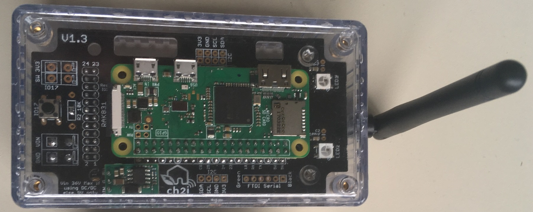
This shield has been created to help wiring between Raspberry PI Zero and RAK831 LoraWan concentrator Gateway and to be able to put the whole thing into a enclosure..
Then I decided to add some funky stuff like:
Major updates in V1.5a
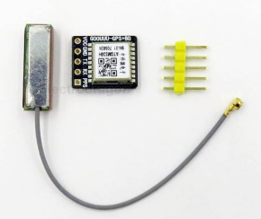
- Added connector to put a Tiny GPS breakout board
- Added switch/jumpers to select PI Serial to be connected to FTDI connector or from GPS RX/TX
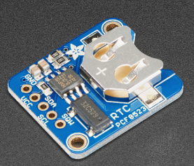
- Added footprint for RTC components or Adafruit Breakout (when used in local LoRaWAN server without Internet connexion)
- Added a LED on
GPIO4GPIO26 to light when GW is off so we can remove power safely (or whatever purpose) - Connected GPS PPS signal on GPIO4 and added a LED on this signal
- due to space constraints because of new features, some options to put PTH components have been removed
Minor tweaks in V1.4
- Labeling error on top silk for Murata OKI-78SR-5 (VIN VOUT were revesed) but correct on bottom silk
- Added solder bat to be able to reverse 3V3/GND and/or SCL/SDA on I2C-1 connector
- Moved FTDI connector to lower position
- Added I2C connector SILK number to identify them better
- Added a LED on GPIO4 to light when GW is off so we can remove power safely
Minor tweaks in V1.3b
- Reversed side of Murata OKI-78SR-5 to let some place for big OLED
- Changed solder pad default power to use DC/DC
- Inversed the 2 OLED connectors to better seeing of RAK LED
- Adjusted opening to see RAK LED to a better position
Since V1.3
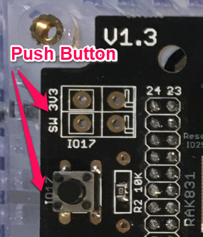
- Push button on GPIO17 to be able to shutdown PI Locally
- Added FTDI connector to be able to take hand on PI console when in enclosure (lost network or whatever, no more need to get all off the enclosure and connect HDMI cable to see what's going on)
- Added footprint for excellent Murata OKI-78SR-5 DC/DC 5V
- Footprint for RAK831 LoraWan concentrator (main goal)
- I2C connectors to be able to add internal/external sensors or OLED such as BME280, SI7021, HTU21D SSD1306
- Power with terminal block
- 2 visual WS2812B Leds
- Easy to build and solder, 0805 or PTH components
- Holes to fix board on enclosure or other support
- quick fix connector, you can plug/unplug PI Zero without soldering
Tiny GPS breakout board, buy there
Tiny Adafruit RTC board, buy there
No specific documentation for now, it's just a kind of wiring helper, please see Gateway section on TTN Learn and also on TTN Forums for more information on these gateways.
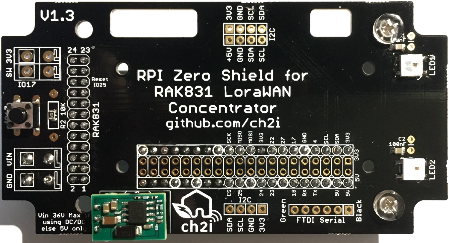
You can power the board with 5V going to Raspberry PI USB power directly or connecting 5V to the terminal blocks named VIN/GND, in this case use a descent 5V power supply.
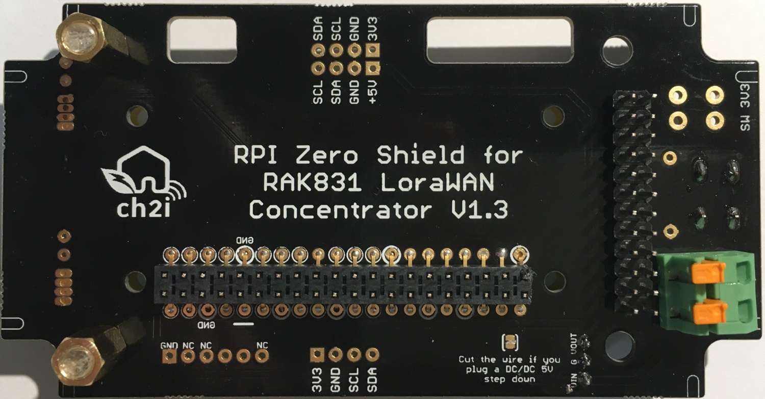
You can also use a Murata DC/DC Step down (see BOM), in this case you can power the board from DC 7V to 36V, this is what I do each time. To use this feature you need to cut the trace on bottom side of PCB that connect VIN to 5V (vout).
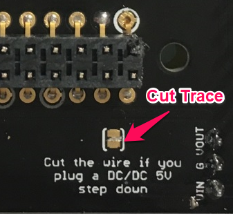
Since V1.3b+ the trace is not connected anymore. This means that Vin and Vout are not connected anymore. So if you don't use DC/DC and powering with 5V, you need to put some solder on the pad to connect vout to vin (5V).
The push button is connected between 3V3 and GPIO17. GPIO17 has a 10K pull down to ground so when pressed GPIO17 become High. The button can be soldered on board, or connected to the Terminal Blocks if you want to put an external one if you have the board in a closed enclosure for example.
Push button management is done my the monitoring service installed by the setup below
Led management is done my the monitoring service installed by the setup below
Please follow the installation documented on the dedicated repository to install all needed and functionnal software:
- Initial configuration
- Multi Protocol Packet Forwarder
- Monitoring service (Led and Push Button)
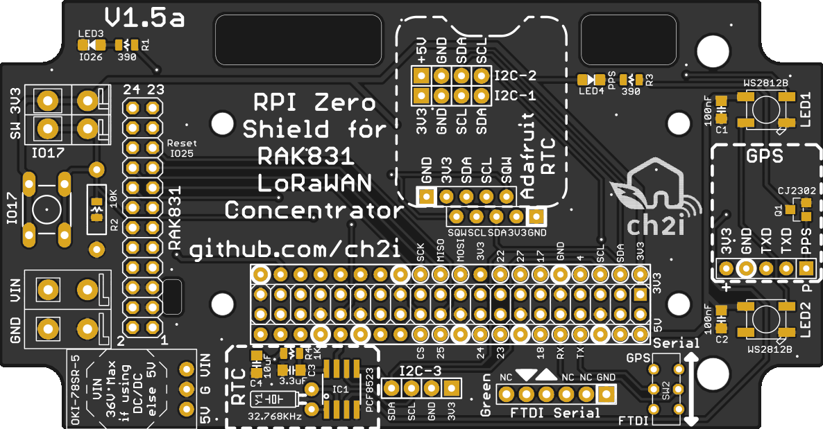
Top side
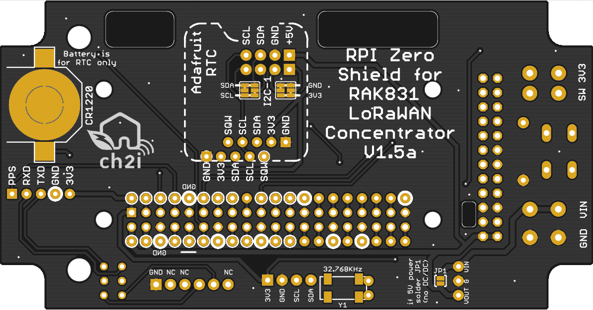
Bottom side
Top side
Bottom side
You can order the PCB of this board at PCBs.io
Please not that there is special PCB version (not released yet) that fit in an indoor enclosure like the ones you can find on ebay. Search on ebay for 100x68x50mm IP66 Waterproof or 100x68x50mm IP66 Waterproof clear to find them.
- V1.3 For outdoor enclosure (smaller PCB)
PCBs.io give me some reward when you order my designed boards from their site. This is pretty good, because I can use these rewards to create and design new boards and order boards for a discounted price, so if you don't care about PCB manufacturer please use PCBs.io.
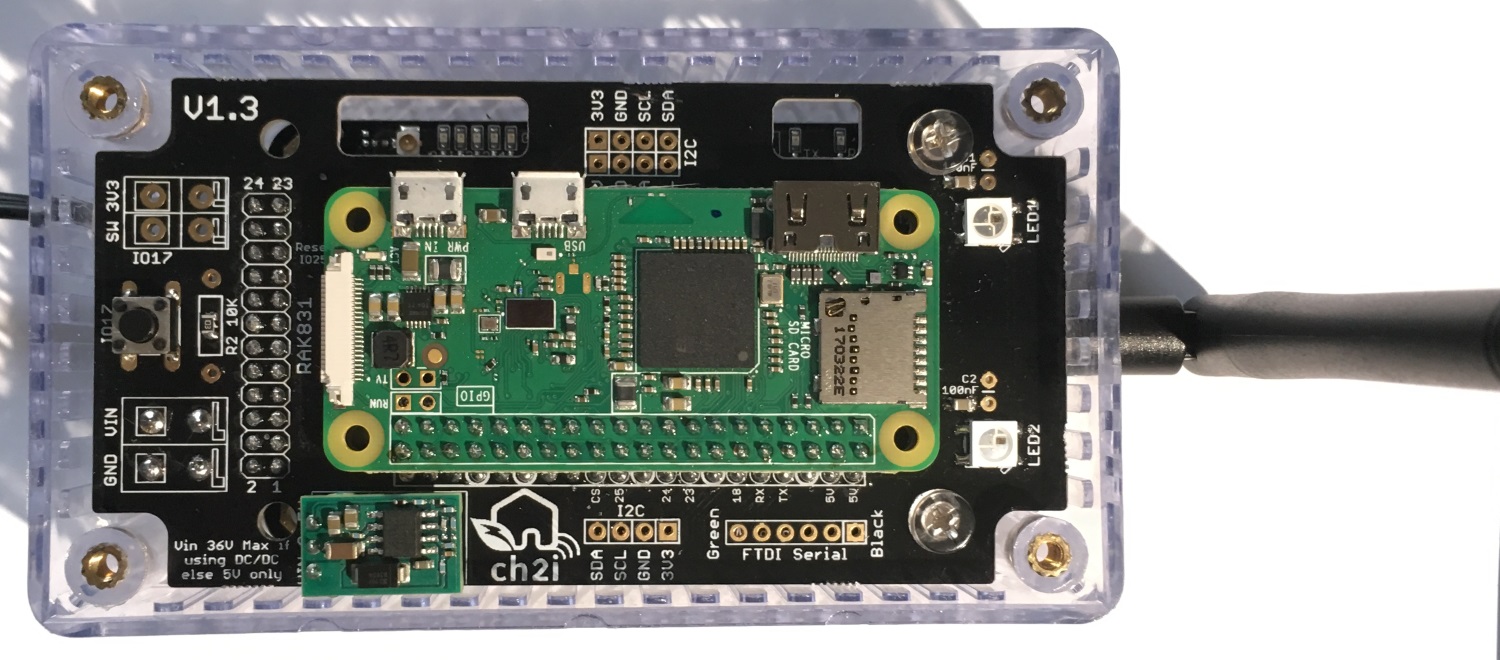
With the samtec connector you can put the PI Zero on top or bottom, depending on your choice, just solder the sametec connector to the PCB side you need. You can also avoid connector soldering the PI directly on the board.
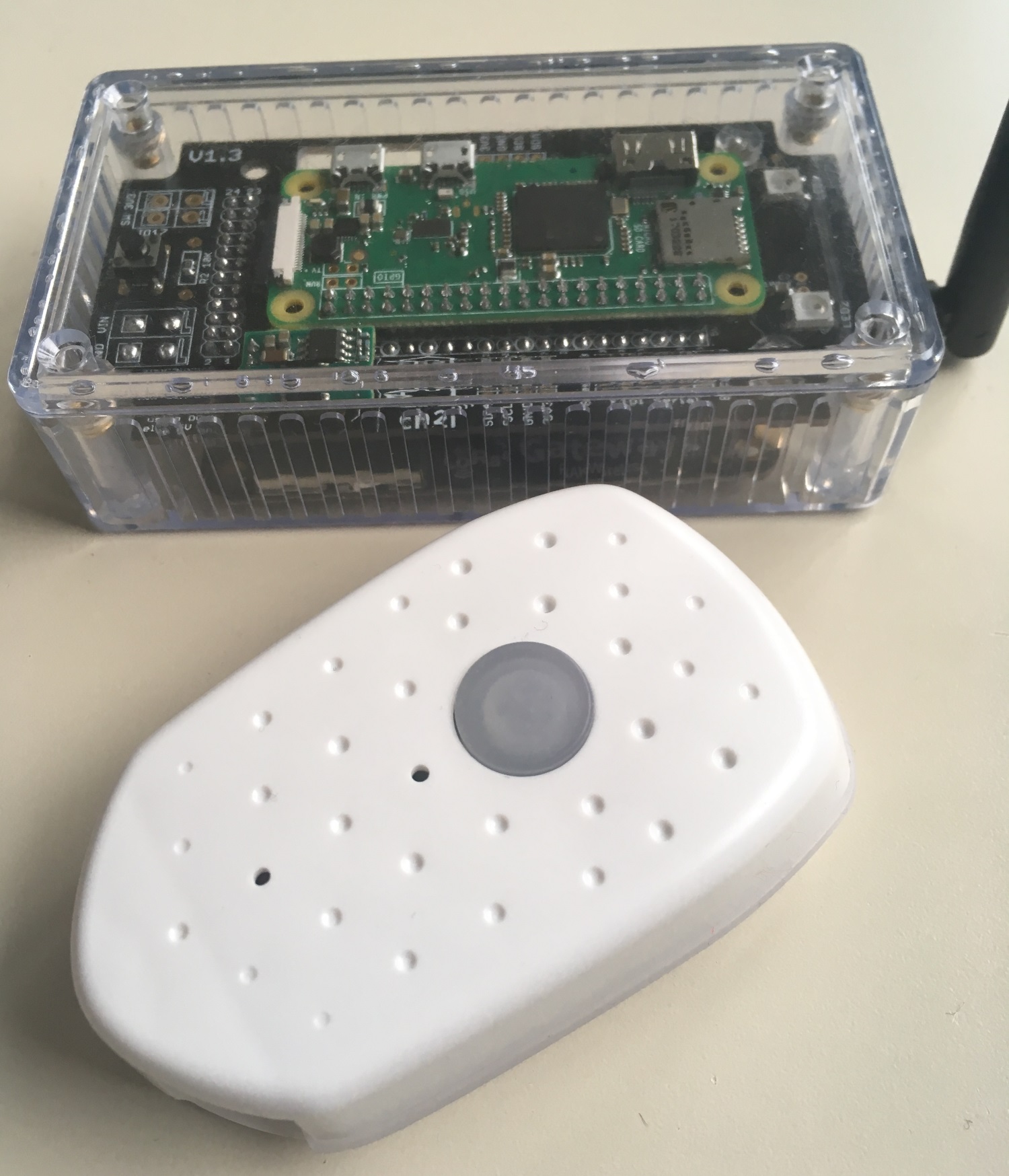
And here it is near to The things node.
Click on image to see the video

Nothing fancy, all components are 0805 and/or PTH and can be ordered almost anywhere (digikey, mouser, radiospare, ...). use only what you need dependings on what you want to do. You can find lot of components on ebay or aliexpress, but since vendors are often ephemere, I put for reference the BOM on well known providers.
Here is the octopart BOM
If you have good reference for standoff like this, just let me know.

This work is licensed under a Creative Commons Attribution-NonCommercial 4.0 International License
If you want to do commercial stuff with this project, please contact CH2i company so we can organize an simple agreement.
See news and other projects on my blog