The goal of this project is to simulate and test the attitude control system of a 1U CubeSAT. In the end, the CubeSAT will be given fake sensor data from the 3D simulation and the reaction of the attitude control system will be read and fed into the simulation.
The CubeSAT's orbit will have an altitude of 400km - 1000km. It will be equipped with a variety of sensors, including a three-axis gyroscope sensor, a three-axis magnetometer and a (maybe selfbuild) horizon sensor. The only way it will be able to control its attitude is by using the three magnetorquers it is equipped with.
The 3D Simulation is written in Matlab and considers the following effects.
- the gravitational force of the earth causing the CubeSAT to orbit. Only the raw force to the satellite's center of mass is regarded, the torque created by a specific distribution of mass in the satellite is ignored at the moment. This could be implemented at a later point of time when the detailed construction plan is known.
- the force and torque of the earth's magnetic field on the the magnetorquers.
The magnetic field is regarded as being created by a magnetic dipole. The direction of the magnetic dipole moment is assumed to be the same as the rotation axis and the strength is (according to own estimations) set to 10^23 A*m². The magnetic field created by such a magnetic dipole moment looks like this (By Bdushaw (Own work) [CC BY-SA 4.0 (http://creativecommons.org/licenses/by-sa/4.0)], via Wikimedia Commons):
The resulting 3D magnetic field looks like this:

The magnetic flux density vector is calculated by using the the formula from this reference.
Thus far it is not finally clear if this model is accurate enough and especially if the "horizontal scale" of the field matches the earth's one.

Currently we have not implemented any virtual sensors and just feed the control algorithm the information (angular velocity, magnetic field strength etc.) straightly from the simulation. In the future we plan to add noise and offset values to the sensor data in order to recreate a simulation closer to the real world.
Now the voltages calculated by the control algorithm cause a slow but realistic increase in the current due to self-induction.
The only way to change the satellite’s attitude is by powering the magnetorquers. These can create a torque resulting in an angular acceleration. The problem however is that the torque is always perpendicular to the magnetic flux density vector (the formula is t = m x B). So the satellite cannot be rotated arbitrarily. In fact, if the satellite is rotating around the axis parallel to the magnetic field vector the magnetorquers cannot not change that at all. Luckily the CubeSAT is orbiting the earth with an inclination. While the amount of inclination is not known yet it is reasonable to expect the inclination to be greater than zero. So while the satellite may rotate around the axis parallel to the magnetic field vector at one point, due to the inclination the orientation of the magnetic field vector changes as the CubeSAT moves further on its orbit. Therefore it is always possible to change the rotation velocity according to any given axis, at least in theory.
In the detumbling part of the attitude control algorithm the goal is the stop any rotation thereby stabilize the attitude of the satellite.
The first approach arises from the knowledge that a strong acceleration is needed to stop a higher rotation velocity and in order to adjust the velocity finely a weaker acceleration might be helpful. So the strength of the target torque is set in proportion to the amount of the angular velocity.
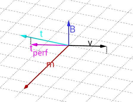
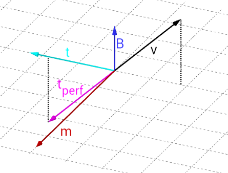
Now the direction of the target torque has to be determined. Unfortunately, only torques perpendicular to the magnetic field vector can be created. Therefore the perfect torque and the real torque do not align in the general case. Currently, the direction of our magnetic dipole moment created by the magentorques points in the inverse direction of the cross product of the magnetic field vector and the rotation axis. These two images show how the resulting torque t correlates to the “perfect torque” tperf when the rotation axis v is nearly perpendicular to the magnetic field vector B and when they are not perpendicular at all.
Although the derivation from the perfect torque is quite large, the important thing to note is that by applying such a angular acceleration the magnitude of the velocity is decreasing.
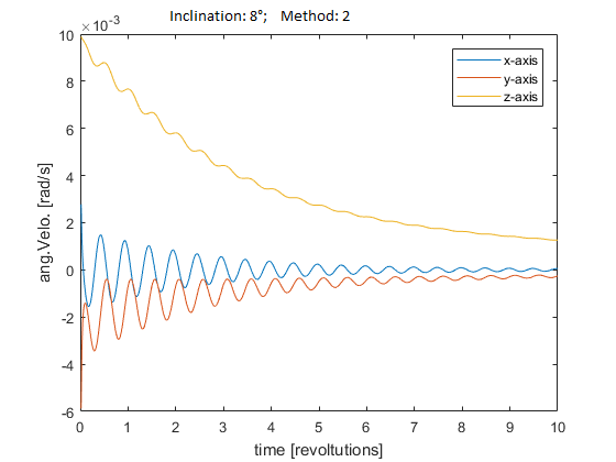
Testing has showed some pleasant results as long as the inclination was high but unsatisfying with lower inclination:
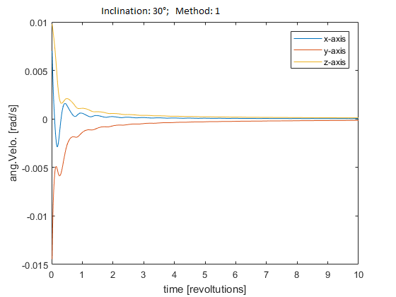
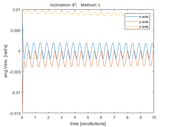
As it has been noted, the angular velocity can be controlled very well when the rotation axis is perpendicular to the magnetic field vector. So tendentially only a small amount of torque is needed because it contributes mostly to the desired rotation. But when the rotation axis is not perpendicular to the magnetic field vector only a small amount of the generated torque contributes to the desired outcome. Therefore the amount of torque generated should be higher in this case.
That is the main idea of the second approach. While a too strong torque results in an oscillation of the velocity a torque that is too weak fails to change the velocity quick enough. With the capability of tuning the strength of the magnetorquers depending on the angle between the rotation axis and the magnetic field vector the torque can be adjusted more precisely to the needs. The results look promising; the detumbling in a 8 degrees orbit works far better than before: