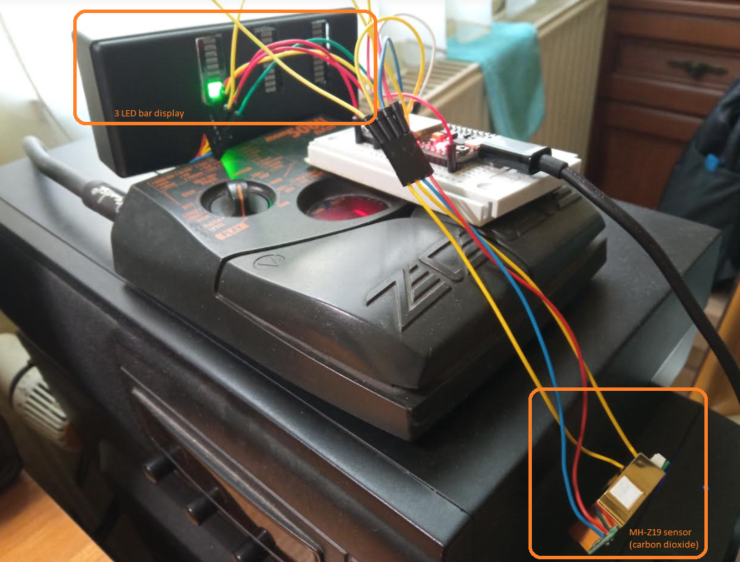
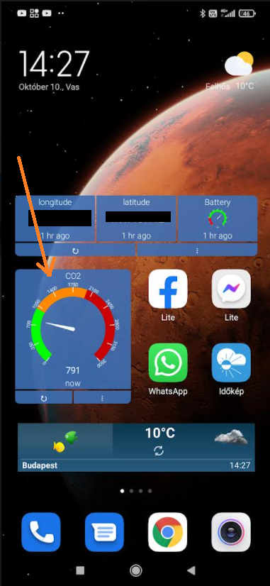
ESP32 device using MQ-6 (LPG gas), MQ-7 (CO) and MH-Z19 (CO2) sensors to collect air quality data, and feed to ThingSpeak, and display on 3x10 segment LED bar.
The device right now is wired on a breadboard, but I am planning to assemble a PCB and put it into a plastic case. It can be hidden anywhere in the room, connected to a standard 5V micro-USB as power supply.
Project on Hackster.io: https://www.hackster.io/akossereg/room-s-carbon-dioxide-level-on-smartphone-4586b1
Find configs in include/config.h, such as:
- WIFI username/password - device will connect to your local wifi network to be able to send data to ThingSpeak
- ThingSpeak write API key
- Connect analog output of MQ-6 sensor to
GPIO 36(seemq_sensors.cchannel usage) - Connect analog output of MQ-7 sensor to
GPIO 39 - Connect MH-Z19 device's TX to
GPIO 34, and RX toGPIO 26 - Connect LED bar display component:
- VCC should be 3.3V
- DATA to
GPIO 25 - CLK to
GPIO 33 - LATCH to
GPIO 27
Components:
- 3x LED bar: https://www.hestore.hu/prod_10041689.html
- 4x Shift Register: https://www.hestore.hu/prod_10021551.html
- 5x 510 Ohm and 5x 1k Ohm resistors
One shift register can drive 8 LEDs, so we need 4 (4x8 = 32) to cover 3x10 LEDs. Shift registers should be daisy chained:
        SN74HC595
        _________
  B ---|(1)      |--- VCC (3.3V)
  C ---|  Shift  |--- Output A
  D ---|   Reg.  |--- DATA
  E ---|         |--- GND
  F ---|         |--- LATCH
  G ---|         |--- CLK
  H ---|         |--- VCC
 GND---|_________|--- Output H' (this goes to the next shift register's DATA)
LED bar display should be connected like this:
     LED bar      Resistors

  +--[ Red    ]--[ 510 Ohm ]--- Output B
  |--[ Red    ]--[ 520 Ohm ]--- Output A (of Shift reg. 2)
  |--[ Yellow ]--[ 520 Ohm ]--- Output H
  |--[ Yellow ]--[ 520 Ohm ]--- Output G
  |--[ Yellow ]--[ 520 Ohm ]--- Output F
  |--[ Green  ]--[ 1k Ohm  ]--- Output E
  |--[ Green  ]--[ 1k Ohm  ]--- Output D
  |--[ Green  ]--[ 1k Ohm  ]--- Output C
  |--[ Green  ]--[ 1k Ohm  ]--- Output B
  |--[ Blue   ]--[ 1k Ohm  ]--- Output A (of Shift reg. 1)
  |
  |
 GND

