Comments (6)
 askuric
commented on May 31, 2024
askuric
commented on May 31, 2024
Hey @shiftux ,
I have never tried the library on the arudino mega1280. This board does not have the high frequency pwm configuration implemented, but this will not prevent it from working.
Which version of the shiled do you have?
Here is the documentation link to exaplain how to configure the board pinout, it also suggest you some pins depending on the board you will be using it with and the sensors you will be using:
https://docs.simplefoc.com/pads_soldering
You will need to solder the pads on the bottom side of the board to choose pwmA, pwmB, pwmC pins as well as the enable pin for the driver. You will have to do the same thing for the encoder A, B and index (I) if you have one. Let me know if you need more assistance if you miss some info from the docs.
- The board supplies the 5V to the 5V pin of the Arduino not VIN ( this was made for the arduino uno really, later I figured out that this feature is not supported on Arudino DUE and stm32 Nucleo so I've chnaged it to VIN (but it will be providing 8V no longer 5V). If this does not work for your board you can connect a jumber in between 5V pin and VIN, maybe this will help.
- Serial connection should work, did you enable
Serial.begin(some value);in the code? What code are you running actually? - You will find the examples in the docs link I've pasted earlier, let me know if you need more info.
- This should not be a problem in your case. If you use I2C devices make sure to connect them to the analog pins
- You will choose either pin 7 or pin 8 when soldering ocnnections and that one you should provide to the
BLCMotor3PWMclass.
Your motor and sensor combinations will work fine with the library, and this board, what is the resolution of the encoder that you've bought?
Let me know how it goes!
from arduino-foc-reaction-wheel-inverted-pendulum.
 shiftux
commented on May 31, 2024
shiftux
commented on May 31, 2024
@askuric
Thanks for your detailed explanation! - This helped!
Indeed I did not read enough of the documentation. I read the phrase All the Arduino SimpleFOCShield boards will be initially tested and they will be shipped with initial configuration in the doc you linked. And from that I concluded that all the solder pads were just there to CHANGE something from the default config. I didn't understand that the pwm and encoder pin selectors needed to be soldered in any case.
I got the motor to spin at 2V speed (voltage controlled) in a very simple setup. So I'm confident the rest will work.
Serial connection does in fact work, I just did not realize that the FOC init functions took that long :) after that I get output.
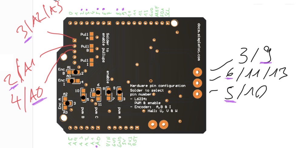
I think what would have helped me to understand the wiring is a diagram like the one I attached. This makes it clear for me to see what pins are used and exposed where on the board (in purple what the docs call "Suggested pinout: Single board", which corresponds to the soldered pads on the image).
The only issues that remain for me are:
- The power supply to the board I did not get to work with a jumper cable from 5V to VIN...
- When I have the shield attached, I can not program the Arduino. I get an error:
avrdude: stk500_paged_write(): (a) protocol error, expect=0x14, resp=0x10. Is there something connected to the TX/RX pins?? - The encoders I got lack a bit of documentation. I am not sure if I need pull up/down resistors for those. Would you know how I could find that out?
Thanks for your help!
from arduino-foc-reaction-wheel-inverted-pendulum.
askuric
commented on May 31, 2024
Hey @shiftux ,
You are indeed completely right!
I will make sure to update the docs, and I stopped shipping the boards with the initial configuration due to the fact that the conductive ink I use for testing somehow made people more confused than it actually helped :D
Ok its great to hear that you actually have voltage control. This is basically all you need for the project of inverted pendulum. Is you mega1280 making a lot of noise? It should not have high frequency pwm signal, you should be able to hear the wining quiet loudly?
- Which board version do you have? Is it v1 or v2? Does the board have the voltage regulator, only the v2.0+ have the voltage regulator, the earlier versions will not power your Arduino.
- There is nothing connected to the pins
D0andD1, I am not sure why this happens! I did not have such problems so far really, I will look into it and I'll let you know as soon as I find something out. Did you try to disconnect the motor and when you program the board? - You could measure the resistance in between
A,Bpins and5Vpin of the encoder. If it has cca 1-5kOhm resistance it already has a pull-up. But if the encoder works in voltage mode, you are probably all set, usually if they need the pull-up they will not work at all before you enable it.
Let me know how it goes :D
from arduino-foc-reaction-wheel-inverted-pendulum.
shiftux
commented on May 31, 2024
Again, thanks for the detailed answer!
I'm using the FOC shield V1.3.3. I also tried it with an Arduino Uno now, but still no power over the VIN pin. Must be related to the version of the board as you mentioned.
Also the upload works better with the Arduino Uno, compared to what I mentioned with the mega.
Regarding the encoders, I don't measure a resistance between 5V and the A/B signal. But I did find the datasheet, where it is mentioned that there is a 2.5kO on the output, so I didn't solder anything.
All in all the electronics and circuit are OK now and working for the pendulum example.
After tuning the LQR constants a bit i get a beautifully stabilized pendulum!
thanks for your help!
(OK for me to close this issue)
from arduino-foc-reaction-wheel-inverted-pendulum.
askuric
commented on May 31, 2024
Hey @shiftux ,
Sorry for a late response!
Yes version 1.3.3 does not have the voltage regulators, the versions v2.0+ do have them.
I'm really happy that you have made it work and that you're satisfied with the results. :D
Unstable dynamical systems are a passion of mine and each time I am able to make one of them stable using the magic of control algorithms it makes me a happy man.
And being able to share this project with other people just completed the experience.
Cheers!
from arduino-foc-reaction-wheel-inverted-pendulum.
shiftux
commented on May 31, 2024
Hehe the thanks goes to you!
Very easy to get it done with all your documentation and quick help on
github.
If I have some more time I'll try a few different control strategies. And
inertia configurations...
Best
…On Mon, Feb 15, 2021, 00:06 Antun Skuric ***@***.***> wrote:
Hey @shiftux <https://github.com/shiftux> ,
Sorry for a late response!
Yes version 1.3.3 does not have the voltage regulators, the versions v2.0+
do have them.
I'm really happy that you have made it work and that you're satisfied with
the results. :D
Unstable dynamical systems are a passion of mine and each time I am able
to make one of them stable using the magic of control algorithms it makes
me a happy man.
And being able to share this project with other people just completed the
experience.
Cheers!
—
You are receiving this because you were mentioned.
Reply to this email directly, view it on GitHub
<#2 (comment)>,
or unsubscribe
<https://github.com/notifications/unsubscribe-auth/ABPK4YSQF2XQLBXWORSJ5M3S7A3OXANCNFSM4XIUWLMA>
.
from arduino-foc-reaction-wheel-inverted-pendulum.
Related Issues (9)
- 2nd encoder connection HOT 2
- Can this be achieved using a gyro? HOT 5
- Mounting Encoder for iPower Motor GM4108H-120T HOT 1
- How to tune the LQR parameters precisely? HOT 2
- Mounting of encoder HOT 1
- Code error HOT 3
- swing up code HOT 1
- please i need your help HOT 3
Recommend Projects
-
 React
React
A declarative, efficient, and flexible JavaScript library for building user interfaces.
-
Vue.js
🖖 Vue.js is a progressive, incrementally-adoptable JavaScript framework for building UI on the web.
-
 Typescript
TypeScript is a superset of JavaScript that compiles to clean JavaScript output.
-
TensorFlow
An Open Source Machine Learning Framework for Everyone
-
Django
The Web framework for perfectionists with deadlines.
-
 Laravel
A PHP framework for web artisans
-
D3
Bring data to life with SVG, Canvas and HTML. 📊📈🎉
-
Recommend Topics
-
javascript
JavaScript (JS) is a lightweight interpreted programming language with first-class functions.
-
web
Some thing interesting about web. New door for the world.
-
server
A server is a program made to process requests and deliver data to clients.
-
Machine learning
Machine learning is a way of modeling and interpreting data that allows a piece of software to respond intelligently.
-
Visualization
Some thing interesting about visualization, use data art
-
Game
Some thing interesting about game, make everyone happy.
Recommend Org
-
Facebook
We are working to build community through open source technology. NB: members must have two-factor auth.
-
Microsoft
Open source projects and samples from Microsoft.
-
Google
Google ❤️ Open Source for everyone.
-
Alibaba
Alibaba Open Source for everyone
-
D3
Data-Driven Documents codes.
-
Tencent
China tencent open source team.
from arduino-foc-reaction-wheel-inverted-pendulum.