Comments (112)
 NikiSchlifke
commented on July 16, 2024
7
NikiSchlifke
commented on July 16, 2024
7
try kicad i think this could open it
Probably not.
A pcb layout isn't sufficient anyway, for open hardware we need the circuit diagram, the part libraries and the layout.
from ender-3.
 MachineryEnchantress
commented on July 16, 2024
7
MachineryEnchantress
commented on July 16, 2024
7
Guys, it's literally just me doing this and there's a million other things going on. Unless your 3D printing parts for your failing iron lung cut me a little slack and give it some time😉
from ender-3.
 RudolphRiedel
commented on July 16, 2024
5
RudolphRiedel
commented on July 16, 2024
5
It is a start, I was more interested in the controller. And with the wiring of the box I tried to figure out a way to add an auto-bed-level sensor more elegantly to the control-box.
Soldering QFNs is not really that difficult. An affordable hot-air station, flux, something to mask off the rest of the nearby area of the board like capton-tape.
The A4988 only have a QFN-28 case and the board has only two layers, so these should come of quite easily.
Regarding tweaking, I was thinking about changing the config for the Z-Stepper from 1/16 steps to full steps.
And now that we have the layout I can check that in detail without the need to remove the heatsinks.
It turns out that each stepper driver has resistors on every single config line including MS1, MS2 and MS3 which control the microstepping resolution.
I could easily remove R35, R36 and R37 and connect their pins that lead to U7 with GND.
Sure that reduces the resolution of the Z-axis to 0.04 mm per step and you have to keep that in mind with the layer-heights. But going full step gives it more strength.
Or in other words, Creality delivered, if not all than most of it and in some regards with a suprising level of detail. We can hope that they are so kind to provide even more information but it is up to the community now to take part in this.
Stop demanding that everything is handed to you, apreciate what you got and do something with it!
And no, I am not adressing you specifically with this Aleks, more the community overall. :-)
I did not like the supplied BOM, so I exported a new one and started editing it.
Ender-3_BOM.xlsx
Miss something? Add it!
from ender-3.
MachineryEnchantress
commented on July 16, 2024
4
I agree KiCAD would be best, I'll see if something can be done.
from ender-3.
RudolphRiedel
commented on July 16, 2024
3
Repairability, exactly.
In the meantime this could be helpfull: https://github.com/RudolphRiedel/CR-10_wiring
I started to draw a schematic for the CR-10 controller-box a while ago, the whole thing including the pcb.
This is as complete as I needed it to be so far.
And the Ender-3 has the same controller-board as the CR-10, well at least later models came with the V1.1.2 version of the board we see in the Ender-3.PCB now.
With the PCB data I could easily improve my schematic further but at the same time I would prefer if Creality supplies the original schematics.
from ender-3.
 DuncanAmos
commented on July 16, 2024
2
DuncanAmos
commented on July 16, 2024
2
Urs I don't think anyone would disagree with you that schematics and board
files for all the popular packages would be ideal...
Natalie is doing her best but, as she freely admits, she's out of her
depth, so it's up to us to step up and make the process easier.
What's the first thing we need to know? Which software package are Creality
using to generate the schematic and board files - right? That's something
that Natalie can probably discover fairly easily.
Once we know that, then Natalie may be able to obtain 'latestVersion.abc'
and 'latestVersion.xyz' files, from which we can (hopefully) create
conversions for other software packages and provide them here, with
supporting information.
A specific request is likely to get a more positive and helpful response.
On a slightly different angle - why would you want to swap out the Atmel 8
bit processor for an ESP32?
Octoprint does a fantastic job of networking the printer already (and is a
'de facto standard') and is there really a requirement for 'more power' in
a device that is, basically, driving stepper motors and
monitoring/controlling two temperatures? All that is well within the
capabilities of the existing hardware.
I can see a need to split out the two fans, but beyond that, the existing
hardware works and, in general, works very well - even if it is close to
using all the available memory.
On Wed, 15 Aug 2018, 11:03 Urs, ***@***.***> wrote:
I'm a happy user of Altium and my idea is to change the Atmel 8bit
processor to ESP32 for more power of the printer and maybe (later) for
network compatibility. But it is exhausting and time-consuming to develop
the circuit diagram from the board. So it would be great if the documents
were complete. So that the community could participate in the development
of Ender, CR10 and other...
—
You are receiving this because you commented.
Reply to this email directly, view it on GitHub
<#2 (comment)>,
or mute the thread
<https://github.com/notifications/unsubscribe-auth/AXX1IOGTb2xVT22q-AYAd4eRyaoAAOgmks5uQ-PygaJpZM4VBpFN>
.
On 15 Aug 2018 11:03, "Urs" <[email protected]> wrote:
I'm a happy user of Altium and my idea is to change the Atmel 8bit
processor to ESP32 for more power of the printer and maybe (later) for
network compatibility. But it is exhausting and time-consuming to develop
the circuit diagram from the board. So it would be great if the documents
were complete. So that the community could participate in the development
of Ender, CR10 and other...
—
You are receiving this because you commented.
Reply to this email directly, view it on GitHub
<#2 (comment)>,
or mute the thread
<https://github.com/notifications/unsubscribe-auth/AXX1IOGTb2xVT22q-AYAd4eRyaoAAOgmks5uQ-PygaJpZM4VBpFN>
.
from ender-3.
MachineryEnchantress
commented on July 16, 2024
2
Any documentation will be in Chinese- if there is any. I'll ask.
Ok- different versions of boards.
If it helps they are using Altium Designer 6.9
This is not an issue of the bosses being reluctant. I'm facing no resistance here, I'm talking directly to the engineer- but he does not speak English and I'm not an engineer. I can say "export in every format you can" and he has- and I've uploaded that. If there is something specific in terms of file suffix, or a screenshot of where to go to get you something useful, an example of some kind, that helps.
This constant assumption of bad faith is exhausting and counter-productive. The same time spent complaining in this thread could have been spent providing instructions that a layperson (me) could pass on.
from ender-3.
RudolphRiedel
commented on July 16, 2024
2
Have you figured out what the difference is between the V1.1.2 and the V1.1.3?
I have both boards on my desk and have not noticed anything else than that EXT-A2 is populated with a capacitor on the V1.1.3 instead of the 3-pin header.
This alone should not be enough for a new board revision, this is merely a change in the BOM.
Also, I forked the Melzi 1.1.2 repository, threw away the "schematic" that does not match the V1.1.2 board and put all the files in it that I still miss in the Ender-3 repository: https://github.com/RudolphRiedel/CR10-Melzi-1.1.2/tree/master/Circuit%20diagram/Motherboard
I also went a step further and started correcting a few bugs with the original .PCB.
Nothing functional though, it still is a V1.1.2, only with less broken data.
from ender-3.
DuncanAmos
commented on July 16, 2024
1
Let's get things in perspective:
Creality did their design in what is probably the best Schematic/PCB/Workflow/3D combined package out there - why the heck wouldn't they?
Eagle is a far more common 'maker/enthusiast/hobbyist' package that KiCAD so, for a moment, let's get real...
Altium does have the capability of exporting their design files in file form called ACCEL ASCII format. This is a data structure EAGLE is able to import. If you wish to import a schematic, click on File/Import/Pcad, Altium, protel option. Then follow the prompts on the dialog box.
I don't know what file imports exist in KiCAD, but maybe this is a start?
Naomi is doing her best - thank you Naoni...
from ender-3.
DuncanAmos
commented on July 16, 2024
1
Well said Naomi...!!!
…On Sat, 15 Sep 2018, 14:37 Naomi Wu, ***@***.***> wrote:
Does anyone want to ask for something without calling the people being
asked liars or making accusations of duplicity in the same post?
—
You are receiving this because you commented.
Reply to this email directly, view it on GitHub
<#2 (comment)>,
or mute the thread
<https://github.com/notifications/unsubscribe-auth/AXX1IPkJY7bm4pasA56cx49TJ5CgcAGtks5ubPR3gaJpZM4VBpFN>
.
from ender-3.
RudolphRiedel
commented on July 16, 2024
1
anyone can translate all pcb to kicad format?
Have you tried the converter mentioned above?
With the .PcbDoc in AD17 format that I attached on July 6th?
is more opensource compiant
No, actually it is not.
If Creality would use some chinese program that no-one outside of china has ever heard of and which would be impossible to even get, they would be still in compliance with open source releasing these files.
There is no obligation attached to convert any of it in the flavor-of-the-year file format.
It would be more conveniant, at least to some people.
In this light we can call ourselfs lucky that Creality is using one of the more widespread CAD tools.
And a lot of others release designs in Altium Designer format.
Plus Naomi already tried to supply more variants.
But AD does not really have exporters.
This one for example: https://github.com/ultimachine/Einsy-Rambo
Would you tell them that they are less opensource compliant because they do not use KiCad?
For what it's worth, my guess is it will be somewhat similar to this for the CR-10
This is a schematic I started from scratch with the available information,
But not exactly focussed on the controller-board but trying to show how it is connected to the printer.
The only reason I did not release the raw project including CR-10_Wiring.SchDoc so far is that it is still missing way to much.
This is an Altium Designer project as well.
from ender-3.
DuncanAmos
commented on July 16, 2024
1
You DID NOT 'kind of have to' post that comment and I'm sure many would
agree that it would have been better if you had never hit the button.
You seem to be under the misconception that there is some kind of
obligation to respond to your continual complaints - there isn't, and
neither is there any obligation on Naomi, or anyone else, to provide
information on here. It is entirely voluntary...
Yes, we all want to see the information from Creality. We want up to date
and correct schematics, board layouts and mechanicals and when Naomi is
able to obtain them, we will have them - of that, I have no doubt.
If you don't like it, go somewhere else...
…On Sun, 14 Oct 2018, 10:58 RudolphRiedel, ***@***.***> wrote:
Okay, it has been four weeks with no reaction again.
I have been ignored here with no clarifications on the attacks towards me
and my tries to get in touch personally to sort out the issue of the
missing files have been ignored as well.
And nothing has been added to the repository, not even the files provided
in the threads.
I really do not like this but I feel that someone has to stand up and
protest and I see no one else doing it.
If this here continues I will take it to a higher authority.
And this sat here for 20+ Minutes in the text-box waiting for me to hit
the "Comment" button, still feels bad but I kind of have to. sorry.
—
You are receiving this because you commented.
Reply to this email directly, view it on GitHub
<#2 (comment)>,
or mute the thread
<https://github.com/notifications/unsubscribe-auth/AXX1IPVe8zwJ_nF4qbFh7YzJI-CqB8LQks5ukvy3gaJpZM4VBpFN>
.
from ender-3.
RudolphRiedel
commented on July 16, 2024
1
I would put that in the realm of luck.
The return path for the current the stepper drivers draw is one issue.
Also the return path for the current that is sent thru the bed and the hotend.
Annother one is the lack of decoupling capacitors at the controllers VCC pins.
The layout for the crystal and most importantly the caps is as wrong as it could be.
The LCD could easily be using the second UART in spi-mode but instead it has to be used with software-spi.
The caps for the stop-switches and the temperature-sensors have unusually high values.
The board-cooling fan beeing coupled to the part cooling fan is a bit scary for printing PETG for example.
There are no passive components at all around the USB, no resistors, no caps, nothing.
There is nothing to counter the massive voltage drop you get when you hot-plug a sd-card due to its inrush current. Okay, four vias and 10 mil traces might play a role in not killing the FT232RL (and there is nothing to indicate that this is by design). With C31 there is only a single 100nF cap for the whole 3.3V trace with the output from the FT232RL, the HC541 and the SD-card.
That the FT232RL is misused to supply the SD-card is annother issue.
ARef tied to VCC is just a minor detail that is wrong.
That is what I found on the spot, there most likely is more.
But hey, it is still working, nothing of the above prevents it from working.
It may have EMV problems, it may be that it could break due to some flaw but it still does the job.
I still have the black pre V1.1.2 installed in my CR-10 and the V1.1.2 installed in my Ender-3.
And while I can not be sure for the CR-10, I put the Ender-3 thru at least 250 hours or printing PETG.
The only sad thing is, all of this could be easily fixed by now if Creality3D would be embracing the idea of Open Source instead of just dumping a bunch of files in a repository and be done with it.
They could be using a much better board by now with close to no or even no additional costs to make and close to no cost to develop it.
At least I would have put in some hours for free to review and redesignt the board.
Instead we still have no answer to the question what has been changed for the V1.1.3 board (and apparently it is only a very minor detail or otherwise it would have been spotted by now).
And we still do not have a schematic for the V1.1.2 board other the one that I reverse-engineered from the board data (and which still may be faulty to wrong data in the board file).
We have the .pdf files over in the CR-10 and the CR10-Melzi-1.1.2 repositories for four months now that do not match the board files in that very same repositories.
These are not the schematics for the board files.
According to the .pdf this is the schematic for the CR-7 Melzi board.
And the picture of the CR-7 board I found shows that it is at least similar, except that it is red, still has the USB power jumper, already has a switching regulator (in DIP) and has a barrel connector installed instead of the screw-terminal.
I really have no idea why this has not been corrected in over four months.
And I have no idea why OSHWA is okay with this - and I asked them to discuss this with Creality3D in order to have this fixed.
CR-7 controller board:

from ender-3.
 Moorviper
commented on July 16, 2024
Moorviper
commented on July 16, 2024
try kicad i think this could open it
from ender-3.
 alekssobolewski
commented on July 16, 2024
alekssobolewski
commented on July 16, 2024
Exactly @NikiSchlifke.
I already tried some programs, and it turned out to be an Altium Designer PCB layout. There is no elements and schematic within the file, so it is basically useless :/
from ender-3.
NikiSchlifke
commented on July 16, 2024
I already tried some programs, and it turned out to be an Altium Designer PCB layout.
Well it's the status quo in industry... as for us Hardware Hackers we really need KiCad
@Creality3DPrinting
@sexycyborg
Have a look at this, maybe this will help us out:
https://github.com/thesourcerer8/altium2kicad
from ender-3.
Moorviper
commented on July 16, 2024
ok it can't open it but it would be nice.
Prusa also switched to kicad
from ender-3.
RudolphRiedel
commented on July 16, 2024
I am missing the schematics as well.
And the Ender-3.PCB is not really an Altium Designer file.
Altium uses .PcbDoc for the layout files.
This is an old Protel format that AD happens to be able to open, really old,
the last Protel version was 99SE. Altium Designer started in 2004.
It barely opens with two warnings generated for AD release 12 and 13.
The only component that has a 3D-model is the connector EXT-A2.
And there are really quite a number of real issues with this design.
But I have no idea if this repository means that we should point these out to Creality in order to let them eventually fix these.
from ender-3.
alekssobolewski
commented on July 16, 2024
And the Ender-3.PCB is not really an Altium Designer file.
@RudolphRiedel Well, maybe it is a Protel file. I just found it opens without a problem in Altium. I'm not a specialist in in, just downloaded a free demo to open a file.
But it does not matter, we need a real schematic and pcb design file created in a free software (like KiCAD).

from ender-3.
RudolphRiedel
commented on July 16, 2024
But it does not matter, we need a real schematic and pcb design file created in a free software (like KiCAD).
While yes, the schematic is missing I do not agree that Creality needs to supply the data in any form they are not actively using. In fact they do not "need" to supply anything and we can considers us lucky already that they supplied as much as they have now.
If asked nicely they may supply a set of .pdf files along with their original design data.
Or someone could just fork this repository and add more files.
And for what purpose do you really "need" the files?
Do you plan to build your own improved PCB? How many out there would do that?
I could do that and already with the data available but the important thing for me here is repairability rather than the need to create a new board from this.
Maybe tweak a few things.
If I wanted a new board I could chose one of the other available options like an Einsy-Rambo which btw. is released as Altium-Designer project.
from ender-3.
RudolphRiedel
commented on July 16, 2024
Here, I just created a project for the board and created an assembly plan with my default output job and not editing anything.
from ender-3.
RudolphRiedel
commented on July 16, 2024
Still yes, I would apreciate a schematic to go with this and I would gladly convert it to a .pdf as well.
from ender-3.
alekssobolewski
commented on July 16, 2024
And for what purpose do you really "need" the files?
Do you plan to build your own improved PCB? How many out there would do that?
Well, my CR-10 is currently connected to MKS L just because I like to do everything on my own, but I have also two not working Creality boards that I broken accidentally. It would be nice to have a schematic to repair the board or add something new. For example improve the 5V supply and maybe change Allegro steppers to Trinamic.
from ender-3.
alekssobolewski
commented on July 16, 2024
Wow! Thanks a lot @RudolphRiedel 😃 I need to replace the stepper drivers, so now I can make an adapter to plug them for example on breadboard (I really have to learn how to properly solder QFN uCs 😛).
from ender-3.
 digitaljunk
commented on July 16, 2024
digitaljunk
commented on July 16, 2024
@RudolphRiedel thanks for your efforts. Great work.
But Creality should fulfill the OSHW certification. Especially when they start to do marketing with that OSHW and Open Source hardware term.
@Creality3DPrinting please publish all files in a file format that can be used for improving the hardware.
from ender-3.
RudolphRiedel
commented on July 16, 2024
The schematic is missing, okay. And probably the project file and a few files around them.
Above the parts library has been requested but the parts are just embedded into the PCB file and can be generated from it: Ender-3_PcbLib.zip
But otherwise releasing the original design files in whatever format is fully compliant with the OSHW definition: https://www.oshwa.org/definition/
For crying out load, they went this far and released their original data.
If it is not in some weird custom format no one ever has heard of you will find someone who can convert it. Regarding converting, I took a quick look at the https://github.com/thesourcerer8/altium2kicad from above and it uses .PcbDoc files from Altium Designer and not .PCB files.
So I just saved the file with AD17:
Ender-3_PcbDoc.zip
Have fun with it and post a KiCad file if you can.
Would you like a set of Gerber files as well?
from ender-3.
MachineryEnchantress
commented on July 16, 2024
I just uploaded a bunch of PCB files that I got in different formats, sorry I'm a bit out of my depth if they are useful, or can be converted to something useful I can also upload please let me know.
https://github.com/Creality3DPrinting/Ender-3/tree/master/Ender-3%20PCB
from ender-3.
 UrsBruetsch
commented on July 16, 2024
UrsBruetsch
commented on July 16, 2024
I'm a happy user of Altium and my idea is to change the Atmel 8bit processor to ESP32 for more power of the printer and maybe (later) for network compatibility. But it is exhausting and time-consuming to develop the circuit diagram from the board. So it would be great if the documents were complete. So that the community could participate in the development of Ender, CR10 and other...
from ender-3.
UrsBruetsch
commented on July 16, 2024
Duncan, thanks for your answer. Yes, you're right, it's not really necessary to change the Atmel to ESP.
And you can go with RasPi and Octoprint. That's a safe solution and it works
but it is also a complicated way to print.
Wifi is defacto a standard in the printer industry.
The ESP also has the advantage that it is much faster than an 8-bit Atmel.
Solutions like Klipper are very charming, but you always have to make the detour via a RasPi and reprogram the printer hardware. Not very comfortable for the people (beginners).
My idea is to update the printer electronics directly to have more speed and comfort without special external hardware and software. The RasPi solution costs more time and money to install and requires a lot of expert knowledge ...
So to bring the printer into a network and improve the speed, the ESP is certainly a good solution.
Octoprint may be a standard, but it was only created to make a difference. The challenge continues. Because stoppage is no progress ...
from ender-3.
RudolphRiedel
commented on July 16, 2024
Sorry Naomi, but I went thru the files and do not see how these would be of any more use than the ones we already had,
The schematic is missing and not more versions of the same board file.
And btw. the board file has no 3D information except for one connector that is not even populated for the Ender-3 but replaced with a capacitor.
Plus the PCB has a few pretty obvious design flaws.
Without schematic and project file and everything else connected to the pcb-project it is however not that easy to contribute anything.
Would Creality even be interested in contributions?
from ender-3.
DuncanAmos
commented on July 16, 2024
I agree that, if you want to 'fiddle' with the Raspberry Pi, it's a
complete pain - 'expert knowledge' doesn't do justice to the grief and
confusion of typing hieroglyphics into the command line. But installing
OctoPi is a painless process.
Sure, a Pi3 is significantly more expensive than an ESP32, but OctoPi runs
quite happily on a Raspberry Pi Zero W and it's virtually 'plug and play'.
I'm unconvinced by 'making it faster'. A 3D printer is limited by its
mechanicals, not by its processing ability - the heavy lifting is all taken
care of in the slicing.
All the printer's doing is moving steppers in response to the G-Code and
monitoring/controlling two heaters - an 8 bit Atmel chip has more than
enough headroom for that, in terms of speed and processing power.
If you priced your time for converting to ESP32 at $10.00 per hour then, by
the time you'd finished the hardware, ported libraries and got reliable,
robust code, you could probably have bought yourself a twin-extruder
printer. (Slightly bogus argument, I'll admit)
I appreciate 'the challenge' but, for me, 'if the wheel works, and works
well, don't waste time and energy reinventing it and end up with a one off'.
I'm a hardware man through and through, but I'd rather develop things to go
into 3D printed enclosures, than redesign the printer and have a heck of a
lot of downtime.
We've digressed... Mia Culpa...
…On Wed, 15 Aug 2018, 15:54 Urs, ***@***.***> wrote:
Duncan, thanks for your answer. Yes, you're right, it's not really
necessary to change the Atmel to ESP.
And you can go with RasPi and Octoprint. That's a safe solution and it
works
but it is also a complicated way to print.
Wifi is defacto a standard in the printer industry.
The ESP also has the advantage that it is much faster than an 8-bit Atmel.
Solutions like Klipper are very charming, but you always have to make the
detour via a RasPi and reprogram the printer hardware. Not very comfortable
for the people (beginners).
My idea is to update the printer electronics directly to have more speed
and comfort without special external hardware and software. The RasPi
solution costs more time and money to install and requires a lot of expert
knowledge ...
So to bring the printer into a network and improve the speed, the ESP is
certainly a good solution.
—
You are receiving this because you commented.
Reply to this email directly, view it on GitHub
<#2 (comment)>,
or mute the thread
<https://github.com/notifications/unsubscribe-auth/AXX1IEkyE-sZaFMHdkMU0lprjTgbcBWCks5uRCgfgaJpZM4VBpFN>
.
from ender-3.
DuncanAmos
commented on July 16, 2024
So, as I suggested earlier, let's see if Naomi can find out what package
Creality are using and then we can see if she can get the specific files
that we need, by specifying the extensions
"This is no better than what we had", "This isn't even used", etc. isn't
helping Naomi get to files that we can actually use when she's out of her
depth by her own admission.
Give the woman a break - she's doing her best...
On 15 Aug 2018 17:46, "RudolphRiedel" <[email protected]> wrote:
Sorry Naomi, but I went thru the files and do not see how these would be of
any more use than the ones we already had,
The *schematic* is missing and not more versions of the same board file.
And btw. the board file has no 3D information except for one connector that
is not even populated for the Ender-3 but replaced with a capacitor.
Plus the PCB has a few pretty obvious design flaws.
Without schematic and project file and everything else connected to the
pcb-project it is however not that easy to contribute anything.
Would Creality even be interested in contributions?
—
You are receiving this because you commented.
Reply to this email directly, view it on GitHub
<#2 (comment)>,
or mute the thread
<https://github.com/notifications/unsubscribe-auth/AXX1IEmNcLX40e6-7hCB6jqYOCqBiJEFks5uREJPgaJpZM4VBpFN>
.
from ender-3.
RudolphRiedel
commented on July 16, 2024
I am pretty sure that Naomi knows what a schematic file is even when not beeing told to lock for a file called .sch or .schdoc.
from ender-3.
 RudyFiero
commented on July 16, 2024
RudyFiero
commented on July 16, 2024
My two cents. Do you really think that Naomi can just go looking for whatever engineering files she can find, that she has access to the engineering documents they have? I would think not.
If she isn't getting the kind of material that would be useful then I think it is because whoever she is dealing with is either not being as helpful, or they have been directed to not provide very useful information.
Without schematic and project file and everything else connected to the
pcb-project it is however not that easy to contribute anything.
I would think they would be open to comments. As far as taking in design files, I would doubt it. It would have to be pretty spectacular work before I would do that. Or the previous work would have to be severely flawed. And I doubt that is the case. I didn't spend too much time looking at the PCB layout but I didn't see big problems. Sure there were a few minor things that I would not have let through, but I'm pretty particular about pcb design.
from ender-3.
DuncanAmos
commented on July 16, 2024
I wasn't implying in any way that Naomi wouldn't know a schematic file,
merely saying that the process of her obtaining the files for those who
seem to disparage her efforts so far, might be easier if we actually knew
what software was in use, and thus which file formats are Involved.
The schematic may be a ".sch" but it's very possible that it's not...
I certainly agree with the first part of Rudy's post and I think that the
second part is a distinct possibility.
Although Creality are supposedly open-sourcing things, that may not be 'all
at once' and it certainly won't be in file formats to suit everyone...
…On Wed, 15 Aug 2018, 23:15 RudolphRiedel, ***@***.***> wrote:
I am pretty sure that Naomi knows what a schematic file is even when not
beeing told to lock for a file called .sch or .schdoc.
—
You are receiving this because you commented.
Reply to this email directly, view it on GitHub
<#2 (comment)>,
or mute the thread
<https://github.com/notifications/unsubscribe-auth/AXX1IN3s2a1jRYiCap4jNh4rkSO39f_2ks5uRI98gaJpZM4VBpFN>
.
from ender-3.
MachineryEnchantress
commented on July 16, 2024
Okay so are we saying the new files I just uploaded are not useful? What format that can be exported from Altium Designer would be useful?
No, I don't know a whole lot about PCBs, no insult there or anything. That's why I'm asking.
from ender-3.
RudyFiero
commented on July 16, 2024
I use a layout program from Mentor Graphics called PADS. It is supposed to open Altium Designer files. The Ender-3.PcbDoc has the right extension and maybe I can open that. Unfortunately I will not be able to try it until tomorrow. I need to use a dongle (hardware key) to run the program and it is at work.
So if I can translate the pcb file I would be able to move things (traces, components) on the layout but I couldn't do anything else with it. I couldn't add or remove parts or connections. For this we would also need the schematic files. I expect it would be called Ender-3.SchDoc.
I have never imported Altium Designer files. I just looked at a couple of Youtube videos on importing them to PADS. It seemed straightforward but I will need to try it.
@UrsBruetsch You said you are a happy user of Altium. Were you able to open any of the pcb files.
There is an online Altium to KiCad converter. http://www2.futureware.at/KiCad/
https://github.com/thesourcerer8/altium2kicad
Since I don't have KiCad I didn't try it.
from ender-3.
RudolphRiedel
commented on July 16, 2024
Okay so are we saying the new files I just uploaded are not useful?
No, we are not saying that the files are not usefull, they might be for someone. :-)
I wrote more usefull than the first file because the new ones do not add any depth for me.
What format that can be exported from Altium Designer would be useful?
Asked like this nothing else.
I already provided a file converted to AD17 to be used for the KiCad Converter.
But it would be nice to know what software Creality is really using, and exactly down to the version.
If that first Ender-3.PCB really is the original design file that Creality is using, they are not even using Altium Designer, they are using its predecessor which was Protel.
And a PCB project always has at least two files, the schematic and the pcb.
Naomi, do you have access to any more files?
In doubt just nake a screenshot and we help point out a few more files.
from ender-3.
RudyFiero
commented on July 16, 2024
I am able to open and translate the Ender-3.PcbDoc file (only did one so far) for my PADS program. Some routing information has been lost (eg. ground plane) but that doesn't surprise me. I will try and have a better look at it tonight.
At minimum the Ender-3.SchDoc file (I assume that is what it is called) is what is needed.
This is the translate log with the notes and warnings.
PADS Layout Translator (Version VX.0) 08/16/18 08:03:09
Copyright (c) 2014 Mentor Graphics Corp. - All rights reserved

------------------------------------------------------------
Input file: C:\Users\rgh\Documents\Ender-3-master\Ender-3 PCB\PCB 5.0 Binary File\Ender-3.PcbDoc
File size: 1851 Kb
File type: Protel PCB Binary Design
File version: 5.0
Output file: C:\Users\rgh\Documents\ender\Ender-3.pcb

[W] Cannot find the Protel / Altium configuration file 'C:\Users\rgh\AppData\Roaming\Altium\advpcb.ini'. Using Protel / Altium Classic Colors for layers.
[W] Cannot load the current color map from the PADS Layout configuration file. Using default colors.
[I] Protel / Altium rule type is not supported in PADS Layout. Rule type ignored: Fanout_Small of kind FanoutControl
[I] Protel / Altium rule type is not supported in PADS Layout. Rule type ignored: Fanout_SOIC of kind FanoutControl
[I] Protel / Altium rule type is not supported in PADS Layout. Rule type ignored: Fanout_LCC of kind FanoutControl
[I] Protel / Altium rule type is not supported in PADS Layout. Rule type ignored: Fanout_BGA of kind FanoutControl
[W] Protel / Altium rules with empty scope are ignored: Clearance_1
[W] Ignored DXP rules that have Unknown layers as operand of scope function on layer KeepOutLayer
[W] Ignored DXP rule scope whose functions, properties, or operators are not supported: InPadClass
[I] Protel / Altium rule type is not supported in PADS Layout. Rule type ignored: PolygonConnect_1 of kind PolygonConnect
[I] Skipped empty text strings at (-2013.54, 317.843)
[W] PADS Layout can not handle individual settings (Remove dead copper) for polygon planes at (-3329.04, 609.843) on TopLayer
[E] Polygon contours are not expandable. Polygons are translated as 2D lines at (-3329.04, 609.843) on TopLayer
[W] PADS Layout can not handle individual settings (Remove dead copper) for polygon planes at (-2235.54, 378.843) on TopLayer
[W] PADS Layout can not handle individual settings (Remove dead copper) for polygon planes at (-2857.54, 341.843) on TopLayer
[W] PADS Layout can not handle individual settings (Remove dead copper) for polygon planes at (-2532.54, 349.843) on TopLayer
[W] PADS Layout can not handle individual settings (Remove dead copper) for polygon planes at (-3966.54, 0) on TopLayer
[W] PADS Layout can not handle individual settings (Remove dead copper) for polygon planes at (-1704.54, 326.843) on BottomLayer
[W] PADS Layout can not handle individual settings (Remove dead copper) for polygon planes at (-3331.04, 608.843) on BottomLayer
[W] PADS Layout can not handle individual settings (Remove dead copper) for polygon planes at (-2235.54, 378.843) on BottomLayer
[W] PADS Layout can not handle individual settings (Remove dead copper) for polygon planes at (-2856.54, 340.843) on BottomLayer
[W] PADS Layout can not handle individual settings (Remove dead copper) for polygon planes at (-2532.54, 350.843) on BottomLayer
[W] PADS Layout can not handle individual settings (Remove dead copper) for polygon planes at (-3606.54, 385.843) on BottomLayer
[W] PADS Layout can not handle individual settings (Remove dead copper) for polygon planes at (-3966.54, 0) on BottomLayer
[W] Solder Mask Tenting is not supported in PADS Layout. The attribute ignored: at (-3430, 656)
[W] Solder Mask Tenting is not supported in PADS Layout. The attribute ignored: at (-3355, 1311)
[W] Solder Mask Tenting is not supported in PADS Layout. The attribute ignored: at (-3471.54, 1456.84)
[W] Solder Mask Tenting is not supported in PADS Layout. The attribute ignored: at (-2206.54, 729.843)
[W] Solder Mask Tenting is not supported in PADS Layout. The attribute ignored: at (-3193.54, 2206.84)
[W] Square holes are not supported and will be translated to round. The diameter will be equal to hole size. at terminal '1' in decal 'D-SMA'
[I] Renamed device name to uppercase letters: Diode renamed DIODE
[I] Renamed pattern name to uppercase letters: Fiducial-A renamed FIDUCIAL-A
[W] Assigned a name to a pin missing a name: $$$1 in device FIDUCIAL-A
[I] Renamed device name to uppercase letters: Fiducial renamed FIDUCIAL
[I] Renamed component name to uppercase letters: Fid3 renamed FID3
[W] Renamed symbols with the same pattern: FIDUCIAL-A renamed FIDUCIAL-A/2
[W] Assigned a name to a pin missing a name: $$$1 in device FIDUCIAL-A/2
[W] Renamed symbols with the same device name: FIDUCIAL renamed FIDUCIAL/2
[I] Renamed component name to uppercase letters: Fid2 renamed FID2
[I] Renamed component name to uppercase letters: Fid1 renamed FID1
[W] Renamed symbols with the same pattern: P4 renamed P4/2
[I] Renamed device name to uppercase letters: 100uF renamed 100UF
[I] Renamed device name to uppercase letters: 4.7uF renamed 4.7UF
[I] Renamed device name to uppercase letters: 100nF renamed 100NF
[I] Renamed device name to uppercase letters: 220nF renamed 220NF
[W] Renamed symbols with the same device name: 100NF renamed 100NF/2
[I] Renamed device name to uppercase letters: 1uF renamed 1UF
[I] Renamed device name to uppercase letters: 330nF renamed 330NF
[I] Renamed device name to uppercase letters: 22p renamed 22P
[W] Renamed symbols with the same device name: DIODE renamed DIODE/2
[I] Renamed device name to uppercase letters: 10k renamed 10K
[I] Renamed device name to uppercase letters: 20k renamed 20K
[I] Renamed device name to uppercase letters: 100k renamed 100K
[I] Renamed device name to uppercase letters: 1k renamed 1K
[I] Renamed device name to uppercase letters: Res2 renamed RES2
[W] Renamed pins with duplicate names: 0 in device TF renamed 0/2
[W] Renamed pins with duplicate names: 0 in device TF renamed 0/3
[W] Assigned a name to a component missing a name: $$$1
[W] Assigned a name to a component missing a name: $$$2
[W] Assigned a name to a component missing a name: $$$3
[W] Renamed pins with duplicate names: 0 in device USB renamed 0/2
[W] Renamed pins with duplicate names: 0 in device USB renamed 0/3
[W] Renamed pins with duplicate names: 0 in device USB renamed 0/4
[W] Assigned a name to a component missing a name: $$$4
[W] Text heights are out of range (0, 1000]. Heights changed to: 0 to 1 at (-22450.5, -9403.16)
[W] Renamed symbols with the same pattern: P2 renamed P2/2
[I] Renamed device name to uppercase letters: Cap renamed CAP
[I] Renamed device name to uppercase letters: Cap Pol3 renamed CAP POL3
[W] Renamed incorrect device name: CAP POL3 renamed CAP_POL3
[I] Renamed device name to uppercase letters: Fuse 1 renamed FUSE 1
[W] Renamed incorrect device name: FUSE 1 renamed FUSE_1
[I] Renamed device name to uppercase letters: Inductor renamed INDUCTOR
[W] Renamed symbols with the same device name: RES2 renamed RES2/2
[I] Dummy components created for free pads: @0 created for (-162.535, 2714.84)
[I] Dummy components created for free pads: @1 created for (-2087.54, 495.843)
[I] Dummy components created for free pads: @0_2 created for (-2736.54, 492.843)
[I] Dummy components created for free pads: @1_2 created for (-2409.54, 496.843)
[I] Dummy components created for free pads: @1_3 created for (-2360.98, 186.843)
[I] Dummy components created for free pads: @1_4 created for (-2557.83, 186.843)
[I] Dummy components created for free pads: @1_5 created for (-2951.54, 186.843)
[I] Dummy components created for free pads: @1_6 created for (-2754.69, 186.843)
[W] Solder Mask Tenting is not supported in PADS Layout. The attribute ignored: at (-3692.54, 834.843)
[I] Dummy components created for free pads: @2 created for (-3692.54, 834.843)
[I] Dummy components created for free pads: @3 created for (-3621.54, 835.843)
[I] Dummy components created for free pads: @1_7 created for (-3520.39, 277.937)
[I] Dummy components created for free pads: @1_8 created for (-3520.39, 275.937)
[I] Dummy components created for free pads: @1_9 created for (-3520.39, 273.937)
[I] Dummy components created for free pads: @1_10 created for (-3520.39, 271.937)
[I] Dummy components created for free pads: @1_11 created for (-3520.39, 269.937)
[I] Dummy components created for free pads: @1_12 created for (-3520.39, 267.937)
[I] Dummy components created for free pads: @1_13 created for (-3520.39, 267.937)
[I] Dummy components created for free pads: @1_14 created for (-3520.39, 265.937)
[I] Dummy components created for free pads: @1_15 created for (-3520.39, 263.937)
[I] Dummy components created for free pads: @1_16 created for (-3520.39, 261.937)
[I] Dummy components created for free pads: @1_17 created for (-3520.39, 259.937)
[I] Dummy components created for free pads: @1_18 created for (-3520.39, 257.937)
[I] Dummy components created for free pads: @1_19 created for (-3520.39, 261.937)
[I] Dummy components created for free pads: @1_20 created for (-3520.39, 259.937)
[I] Dummy components created for free pads: @1_21 created for (-3520.39, 257.937)
[I] Dummy components created for free pads: @1_22 created for (-3520.39, 255.937)
[I] Dummy components created for free pads: @1_23 created for (-3520.39, 253.937)
[I] Dummy components created for free pads: @1_24 created for (-3520.39, 251.937)
[I] Dummy components created for free pads: @1_25 created for (-3520.39, 251.937)
[I] Dummy components created for free pads: @1_26 created for (-3520.39, 249.937)
[I] Dummy components created for free pads: @1_27 created for (-3520.39, 247.937)
[I] Dummy components created for free pads: @1_28 created for (-3520.39, 245.937)
[I] Dummy components created for free pads: @1_29 created for (-3520.39, 243.937)
[I] Dummy components created for free pads: @1_30 created for (-3520.39, 241.937)
[I] Dummy components created for free pads: @0_3 created for (-3520.39, 259.937)
[I] Dummy components created for free pads: @1_31 created for (-3520.39, 455.102)
[I] Dummy components created for free pads: @1_32 created for (-3520.39, 453.102)
[I] Dummy components created for free pads: @1_33 created for (-3520.39, 451.102)
[I] Dummy components created for free pads: @1_34 created for (-3520.39, 449.102)
[I] Dummy components created for free pads: @1_35 created for (-3520.39, 447.102)
[I] Dummy components created for free pads: @1_36 created for (-3520.39, 445.102)
[I] Dummy components created for free pads: @1_37 created for (-3520.39, 445.102)
[I] Dummy components created for free pads: @1_38 created for (-3520.39, 443.102)
[I] Dummy components created for free pads: @1_39 created for (-3520.39, 441.102)
[I] Dummy components created for free pads: @1_40 created for (-3520.39, 439.102)
[I] Dummy components created for free pads: @1_41 created for (-3520.39, 437.102)
[I] Dummy components created for free pads: @1_42 created for (-3520.39, 435.102)
[I] Dummy components created for free pads: @1_43 created for (-3520.39, 439.102)
[I] Dummy components created for free pads: @1_44 created for (-3520.39, 437.102)
[I] Dummy components created for free pads: @1_45 created for (-3520.39, 435.102)
[I] Dummy components created for free pads: @1_46 created for (-3520.39, 433.102)
[I] Dummy components created for free pads: @1_47 created for (-3520.39, 431.102)
[I] Dummy components created for free pads: @1_48 created for (-3520.39, 429.102)
[I] Dummy components created for free pads: @1_49 created for (-3520.39, 429.102)
[I] Dummy components created for free pads: @1_50 created for (-3520.39, 427.102)
[I] Dummy components created for free pads: @1_51 created for (-3520.39, 425.102)
[I] Dummy components created for free pads: @1_52 created for (-3520.39, 423.102)
[I] Dummy components created for free pads: @1_53 created for (-3520.39, 421.102)
[I] Dummy components created for free pads: @1_54 created for (-3520.39, 419.102)
[I] Dummy components created for free pads: @0_4 created for (-3520.39, 437.102)
[I] Dummy components created for free pads: @1_55 created for (-3737.63, 279.992)
[I] Dummy components created for free pads: @1_56 created for (-3735.63, 279.992)
[I] Dummy components created for free pads: @1_57 created for (-3733.63, 279.992)
[I] Dummy components created for free pads: @1_58 created for (-3731.63, 279.992)
[I] Dummy components created for free pads: @1_59 created for (-3729.63, 279.992)
[I] Dummy components created for free pads: @1_60 created for (-3727.63, 279.992)
[I] Dummy components created for free pads: @1_61 created for (-3727.63, 279.992)
[I] Dummy components created for free pads: @1_62 created for (-3725.63, 279.992)
[I] Dummy components created for free pads: @1_63 created for (-3723.63, 279.992)
[I] Dummy components created for free pads: @1_64 created for (-3721.63, 279.992)
[I] Dummy components created for free pads: @1_65 created for (-3719.63, 279.992)
[I] Dummy components created for free pads: @1_66 created for (-3717.63, 279.992)
[I] Dummy components created for free pads: @1_67 created for (-3721.63, 279.992)
[I] Dummy components created for free pads: @1_68 created for (-3719.63, 279.992)
[I] Dummy components created for free pads: @1_69 created for (-3717.63, 279.992)
[I] Dummy components created for free pads: @1_70 created for (-3715.63, 279.992)
[I] Dummy components created for free pads: @1_71 created for (-3713.63, 279.992)
[I] Dummy components created for free pads: @1_72 created for (-3711.63, 279.992)
[I] Dummy components created for free pads: @1_73 created for (-3711.63, 279.992)
[I] Dummy components created for free pads: @1_74 created for (-3709.63, 279.992)
[I] Dummy components created for free pads: @1_75 created for (-3707.63, 279.992)
[I] Dummy components created for free pads: @1_76 created for (-3705.63, 279.992)
[I] Dummy components created for free pads: @1_77 created for (-3703.63, 279.992)
[I] Dummy components created for free pads: @1_78 created for (-3701.63, 279.992)
[I] Dummy components created for free pads: @0_5 created for (-3719.63, 279.992)
[I] Dummy components created for free pads: @3_2 created for (-3716.69, 515.969)
[I] Dummy components created for free pads: @0_6 created for (-3914.09, 259.937)
[I] Dummy components created for free pads: @1_79 created for (-3914.09, 241.937)
[I] Dummy components created for free pads: @1_80 created for (-3914.09, 243.937)
[I] Dummy components created for free pads: @1_81 created for (-3914.09, 245.937)
[I] Dummy components created for free pads: @1_82 created for (-3914.09, 247.937)
[I] Dummy components created for free pads: @1_83 created for (-3914.09, 249.937)
[I] Dummy components created for free pads: @1_84 created for (-3914.09, 251.937)
[I] Dummy components created for free pads: @1_85 created for (-3914.09, 251.937)
[I] Dummy components created for free pads: @1_86 created for (-3914.09, 253.937)
[I] Dummy components created for free pads: @1_87 created for (-3914.09, 255.937)
[I] Dummy components created for free pads: @1_88 created for (-3914.09, 257.937)
[I] Dummy components created for free pads: @1_89 created for (-3914.09, 259.937)
[I] Dummy components created for free pads: @1_90 created for (-3914.09, 261.937)
[I] Dummy components created for free pads: @1_91 created for (-3914.09, 257.937)
[I] Dummy components created for free pads: @1_92 created for (-3914.09, 259.937)
[I] Dummy components created for free pads: @1_93 created for (-3914.09, 261.937)
[I] Dummy components created for free pads: @1_94 created for (-3914.09, 263.937)
[I] Dummy components created for free pads: @1_95 created for (-3914.09, 265.937)
[I] Dummy components created for free pads: @1_96 created for (-3914.09, 267.937)
[I] Dummy components created for free pads: @1_97 created for (-3914.09, 267.937)
[I] Dummy components created for free pads: @1_98 created for (-3914.09, 269.937)
[I] Dummy components created for free pads: @1_99 created for (-3914.09, 271.937)
[I] Dummy components created for free pads: @1_100 created for (-3914.09, 273.937)
[I] Dummy components created for free pads: @1_101 created for (-3914.09, 275.937)
[I] Dummy components created for free pads: @1_102 created for (-3914.09, 277.937)
[I] Dummy components created for free pads: @1_103 created for (-3914.09, 419.102)
[I] Dummy components created for free pads: @1_104 created for (-3914.09, 421.102)
[I] Dummy components created for free pads: @1_105 created for (-3914.09, 423.102)
[I] Dummy components created for free pads: @1_106 created for (-3914.09, 425.102)
[I] Dummy components created for free pads: @1_107 created for (-3914.09, 427.102)
[I] Dummy components created for free pads: @1_108 created for (-3914.09, 429.102)
[I] Dummy components created for free pads: @1_109 created for (-3914.09, 429.102)
[I] Dummy components created for free pads: @1_110 created for (-3914.09, 431.102)
[I] Dummy components created for free pads: @1_111 created for (-3914.09, 433.102)
[I] Dummy components created for free pads: @1_112 created for (-3914.09, 435.102)
[I] Dummy components created for free pads: @1_113 created for (-3914.09, 437.102)
[I] Dummy components created for free pads: @1_114 created for (-3914.09, 439.102)
[I] Dummy components created for free pads: @1_115 created for (-3914.09, 435.102)
[I] Dummy components created for free pads: @1_116 created for (-3914.09, 437.102)
[I] Dummy components created for free pads: @1_117 created for (-3914.09, 439.102)
[I] Dummy components created for free pads: @1_118 created for (-3914.09, 441.102)
[I] Dummy components created for free pads: @1_119 created for (-3914.09, 443.102)
[I] Dummy components created for free pads: @1_120 created for (-3914.09, 445.102)
[I] Dummy components created for free pads: @1_121 created for (-3914.09, 445.102)
[I] Dummy components created for free pads: @1_122 created for (-3914.09, 447.102)
[I] Dummy components created for free pads: @1_123 created for (-3914.09, 449.102)
[I] Dummy components created for free pads: @1_124 created for (-3914.09, 451.102)
[I] Dummy components created for free pads: @1_125 created for (-3914.09, 453.102)
[I] Dummy components created for free pads: @1_126 created for (-3914.09, 455.102)
[I] Dummy components created for free pads: @0_7 created for (-3914.09, 437.102)
[W] Broken traces found and ignored. Broken traces found at (-2948.54, 556.843)
[I] Renamed net name to uppercase letters: NetZ-MOT_4 renamed NETZ-MOT_4
[I] Ignored redundant traces at (-1717.07, 2465.84) - (-1717.07, 2575.25)
[I] Renamed net name to uppercase letters: NetZ-MOT_3 renamed NETZ-MOT_3
[I] Renamed net name to uppercase letters: NetY1_2 renamed NETY1_2
[I] Renamed net name to uppercase letters: NetY1_1 renamed NETY1_1
[I] Renamed net name to uppercase letters: NetY-MOT_4 renamed NETY-MOT_4
[I] Renamed net name to uppercase letters: NetY-MOT_3 renamed NETY-MOT_3
[I] Renamed net name to uppercase letters: NetX-MOT_4 renamed NETX-MOT_4
[I] Ignored redundant traces at (-3318.54, 2484.84) - (-3318.54, 2562.79)
[I] Renamed net name to uppercase letters: NetX-MOT_3 renamed NETX-MOT_3
[I] Renamed net name to uppercase letters: NetW3_2 renamed NETW3_2
[I] Renamed net name to uppercase letters: NetW3_1 renamed NETW3_1
[I] Renamed net name to uppercase letters: NetW2_2 renamed NETW2_2
[I] Renamed net name to uppercase letters: NetW2_1 renamed NETW2_1
[I] Renamed net name to uppercase letters: NetW1_2 renamed NETW1_2
[I] Renamed net name to uppercase letters: NetW1_1 renamed NETW1_1
[I] Renamed net name to uppercase letters: NetU7_8 renamed NETU7_8
[I] Renamed net name to uppercase letters: NetU7_27 renamed NETU7_27
[I] Renamed net name to uppercase letters: NetU7_26 renamed NETU7_26
[I] Renamed net name to uppercase letters: NetU7_23 renamed NETU7_23
[I] Renamed net name to uppercase letters: NetU7_17 renamed NETU7_17
[I] Renamed net name to uppercase letters: NetU7_13 renamed NETU7_13
[I] Renamed net name to uppercase letters: NetU7_12 renamed NETU7_12
[I] Renamed net name to uppercase letters: NetU7_1 renamed NETU7_1
[I] Renamed net name to uppercase letters: NetU6_8 renamed NETU6_8
[I] Renamed net name to uppercase letters: NetU6_27 renamed NETU6_27
[I] Renamed net name to uppercase letters: NetU6_26 renamed NETU6_26
[I] Renamed net name to uppercase letters: NetU6_23 renamed NETU6_23
[I] Renamed net name to uppercase letters: NetU6_17 renamed NETU6_17
[I] Renamed net name to uppercase letters: NetU6_13 renamed NETU6_13
[I] Renamed net name to uppercase letters: NetU6_12 renamed NETU6_12
[I] Ignored redundant traces at (-1896.62, 1813.88) - (-1896.12, 1813.88)
[I] Renamed net name to uppercase letters: NetU6_1 renamed NETU6_1
[I] Ignored redundant traces at (-2214.54, 2484.84) - (-2214.54, 2571.93)
[I] Renamed net name to uppercase letters: NetU5_3 renamed NETU5_3
[I] Renamed net name to uppercase letters: NetU4_8 renamed NETU4_8
[I] Renamed net name to uppercase letters: NetU4_27 renamed NETU4_27
[I] Renamed net name to uppercase letters: NetU4_26 renamed NETU4_26
[I] Renamed net name to uppercase letters: NetU4_23 renamed NETU4_23
[I] Renamed net name to uppercase letters: NetU4_17 renamed NETU4_17
[I] Renamed net name to uppercase letters: NetU4_13 renamed NETU4_13
[I] Renamed net name to uppercase letters: NetU4_12 renamed NETU4_12
[I] Renamed net name to uppercase letters: NetU4_1 renamed NETU4_1
[I] Ignored redundant traces at (-3012.54, 2406.84) - (-3012.54, 2470.84)
[I] Renamed net name to uppercase letters: NetU3_8 renamed NETU3_8
[I] Renamed net name to uppercase letters: NetU3_27 renamed NETU3_27
[I] Renamed net name to uppercase letters: NetU3_26 renamed NETU3_26
[I] Renamed net name to uppercase letters: NetU3_23 renamed NETU3_23
[I] Renamed net name to uppercase letters: NetU3_17 renamed NETU3_17
[I] Renamed net name to uppercase letters: NetU3_13 renamed NETU3_13
[I] Renamed net name to uppercase letters: NetU3_12 renamed NETU3_12
[I] Renamed net name to uppercase letters: NetU3_1 renamed NETU3_1
[I] Ignored redundant traces at (-3821.54, 2476.84) - (-3821.54, 2567.02)
[I] Renamed net name to uppercase letters: NetU2_6 renamed NETU2_6
[I] Renamed net name to uppercase letters: NetU2_4 renamed NETU2_4
[I] Renamed net name to uppercase letters: NetU2_2 renamed NETU2_2
[I] Renamed net name to uppercase letters: NetR_P4_1 renamed NETR_P4_1
[I] Renamed net name to uppercase letters: NetR_P3_1 renamed NETR_P3_1
[I] Renamed net name to uppercase letters: NetR_P1_2 renamed NETR_P1_2
[I] Renamed net name to uppercase letters: NetRP4_2 renamed NETRP4_2
[I] Renamed net name to uppercase letters: NetRP3_2 renamed NETRP3_2
[I] Renamed net name to uppercase letters: NetRP2_2 renamed NETRP2_2
[I] Renamed net name to uppercase letters: NetRP1_2 renamed NETRP1_2
[I] Renamed net name to uppercase letters: NetR37_1 renamed NETR37_1
[I] Renamed net name to uppercase letters: NetR36_1 renamed NETR36_1
[I] Renamed net name to uppercase letters: NetR35_1 renamed NETR35_1
[I] Renamed net name to uppercase letters: NetR34_1 renamed NETR34_1
[I] Renamed net name to uppercase letters: NetR33_1 renamed NETR33_1
[I] Renamed net name to uppercase letters: NetR32_1 renamed NETR32_1
[I] Renamed net name to uppercase letters: NetR31_1 renamed NETR31_1
[I] Renamed net name to uppercase letters: NetR30_1 renamed NETR30_1
[I] Renamed net name to uppercase letters: NetR29_1 renamed NETR29_1
[I] Renamed net name to uppercase letters: NetR28_1 renamed NETR28_1
[I] Renamed net name to uppercase letters: NetR27_1 renamed NETR27_1
[I] Renamed net name to uppercase letters: NetR18_1 renamed NETR18_1
[I] Renamed net name to uppercase letters: NetL1_2 renamed NETL1_2
[I] Renamed net name to uppercase letters: NetE-MOT_4 renamed NETE-MOT_4
[I] Renamed net name to uppercase letters: NetE-MOT_3 renamed NETE-MOT_3
[I] Renamed net name to uppercase letters: NetCP3_2 renamed NETCP3_2
[I] Renamed net name to uppercase letters: NetCP3_1 renamed NETCP3_1
[I] Renamed net name to uppercase letters: NetCP2_1 renamed NETCP2_1
[I] Renamed net name to uppercase letters: NetCP1_2 renamed NETCP1_2
[I] Renamed net name to uppercase letters: NetCP1_1 renamed NETCP1_1
[I] Renamed net name to uppercase letters: NetC39_1 renamed NETC39_1
[I] Renamed net name to uppercase letters: NetC37_1 renamed NETC37_1
[I] Renamed net name to uppercase letters: NetC35_1 renamed NETC35_1
[I] Renamed net name to uppercase letters: NetC33_1 renamed NETC33_1
[I] Renamed net name to uppercase letters: NetC32_2 renamed NETC32_2
[I] Renamed net name to uppercase letters: NetC22_2 renamed NETC22_2
[I] Renamed net name to uppercase letters: NetC22_1 renamed NETC22_1
[I] Renamed net name to uppercase letters: NetC18_2 renamed NETC18_2
[I] Renamed net name to uppercase letters: NetC18_1 renamed NETC18_1
[I] Renamed net name to uppercase letters: NetC14_2 renamed NETC14_2
[I] Renamed net name to uppercase letters: NetC14_1 renamed NETC14_1
[I] Renamed net name to uppercase letters: NetC10_2 renamed NETC10_2
[I] Renamed net name to uppercase letters: NetC10_1 renamed NETC10_1
[I] Renamed net name to uppercase letters: NetB1_2 renamed NETB1_2
[W] Overlapping pads/vias found at (-2735.54, 1875.84)
[W] Overlapping pads/vias found at (-1927.54, 1935.84)
[W] Overlapping pads/vias found at (-3531.54, 1880.84)
[W] Overlapping pads/vias found at (-1928.54, 1879.84)
[W] Overlapping pads/vias found at (-1980.54, 1932.84)
[W] Overlapping pads/vias found at (-1984.54, 1876.84)
[W] Overlapping pads/vias found at (-1148.54, 1882.84)
[W] Overlapping pads/vias found at (-1200.54, 1934.84)
[W] Overlapping pads/vias found at (-3593.54, 1878.84)
[W] Overlapping pads/vias found at (-1201.54, 1880.84)
[W] Overlapping pads/vias found at (-3590.54, 1933.84)
[W] Overlapping pads/vias found at (-2734.54, 1933.84)
[W] Overlapping pads/vias found at (-2794.54, 1931.84)
[W] Overlapping pads/vias found at (-2794.54, 1873.84)
[W] Overlapping pads/vias found at (-1146.54, 1937.84)
[W] Overlapping pads/vias found at (-3530.54, 1935.84)
[I] Ignored redundant traces at (-3481.54, 840.543) - (-3481.54, 871.843)
[W] Broken traces found and ignored. Broken traces found at (-508.535, 1801.84)
[W] Broken traces found and ignored. Broken traces found at (-1049.5, 1947.88)
[W] Broken traces found and ignored. Broken traces found at (-1052.57, 1908.88)
[W] Broken traces found and ignored. Broken traces found at (-1175.62, 2041.93)
[W] Broken traces found and ignored. Broken traces found at (-1315.57, 1927.88)
[W] Broken traces found and ignored. Broken traces found at (-1476.54, 613.843)
[W] Broken traces found and ignored. Broken traces found at (-1655.54, 613.843)
[W] Broken traces found and ignored. Broken traces found at (-1832.57, 1908.88)
[W] Broken traces found and ignored. Broken traces found at (-1833.57, 1947.88)
[W] Broken traces found and ignored. Broken traces found at (-1955.62, 2044.93)
[W] Broken traces found and ignored. Broken traces found at (-2094.5, 1927.88)
[W] Broken traces found and ignored. Broken traces found at (-2166.54, 1074.84)
[W] Broken traces found and ignored. Broken traces found at (-2259.54, 1081.84)
[W] Broken traces found and ignored. Broken traces found at (-2284, 1217)
[W] Broken traces found and ignored. Broken traces found at (-2392.54, 2496.84)
[W] Broken traces found and ignored. Broken traces found at (-2636.54, 1944.84)
[W] Broken traces found and ignored. Broken traces found at (-2637.54, 1905.84)
[W] Broken traces found and ignored. Broken traces found at (-2764.54, 2036.84)
[W] Broken traces found and ignored. Broken traces found at (-2899.54, 1924.84)
[W] Broken traces found and ignored. Broken traces found at (-3210.62, 2488.76)
[W] Broken traces found and ignored. Broken traces found at (-3372, 1464)
[W] Broken traces found and ignored. Broken traces found at (-3430.5, 1908.88)
[W] Broken traces found and ignored. Broken traces found at (-3435.5, 1947.88)
[W] Broken traces found and ignored. Broken traces found at (-3453, 1449)
[W] Broken traces found and ignored. Broken traces found at (-3481.54, 984.843)
[W] Broken traces found and ignored. Broken traces found at (-3560.62, 2041.76)
[W] Broken traces found and ignored. Broken traces found at (-3690.57, 1927.88)
[W] Broken traces found and ignored. Broken traces found at (-3753.54, 1753.19)
[W] Broken traces found and ignored. Broken traces found at (-731.535, 1298.84)
[I] Ignored redundant traces at (-327.535, 150.843) - (-327.535, 250.843)
[I] Ignored redundant traces at (-572.535, 366.843) - (-572.535, 418.843)

1 error(s), 91 warning(s) and 264 note(s) found
Finished on 08/16/18 at 08:03:10
------------------------------------------------------------
Total: 264 note(s), 91 warning(s), 1 error(s)
from ender-3.
RudolphRiedel
commented on July 16, 2024
There are revision 1.1.3 boards out?
#12
Can we please have design files for this one as well?
But regarding repairability and seeing that CR-10 printers are also built with the 1.1.2 boards I would very much apreciate this as additional set of files and have the 1.1.2 file-set also completed.
Edit: or given how similar they are a changelog would do.
Amazon has the 1.1.3 listed:
https://www.amazon.com/Creality-Original-Mainboard-Replacement-Control/dp/B07FYJVW1M
But comparing the picture with the V1.1.2 data I did not see any changes so far.

from ender-3.
UrsBruetsch
commented on July 16, 2024
@RudyFiero Yes, i can open the "Ender-3.PcbDoc" but the Design Rule Check has more then 500 Errors.
I think, with some Work on the PCB-Rules and creating new Nets from connected Copper, it will be a usable PCB-File. And I was able to create a component library from the board - Ender-3.pcbLib
from ender-3.
RudolphRiedel
commented on July 16, 2024
Yes, I can confirm that, I just ran the DRC with AD17 and increased the amount of violations reported to 5000.
Came out with 8 warnings and 629 rule violations.
I would guess though that a good portion of that are more or less false positives due to the file beeing converted from an older version.
But this is just silly:

The connection is not missing, the signal at pin 5 is named incorrectly, it should be SD_SCK or similar.
from ender-3.
UrsBruetsch
commented on July 16, 2024
@RudolphRiedel Jepp, thats an Error (in Altium).
Let's hope there are not too many of these mistakes on the board ...
from ender-3.
RudolphRiedel
commented on July 16, 2024
I would not call that an error in Altium, that one is an error in the data.
I actually wonder now if Creality has a schematic for that board.
from ender-3.
RudolphRiedel
commented on July 16, 2024
A friend asked me something about the FETs on board and so I had a closer look.
First is that these are named REP30N06LE in the board and the BOM while it is likely that these are RFP30N06LE.
Okay, we have an external FET for the bed and the fan does not draw much power which leaves the hot-end FET sending some amperes thru the board.


Looking at the GND from the board though I find no solid connection between the three FETs and the GND connector on the board from the PSU.
The same applies to the stepper drivers.
from ender-3.
 adamtegen
commented on July 16, 2024
adamtegen
commented on July 16, 2024
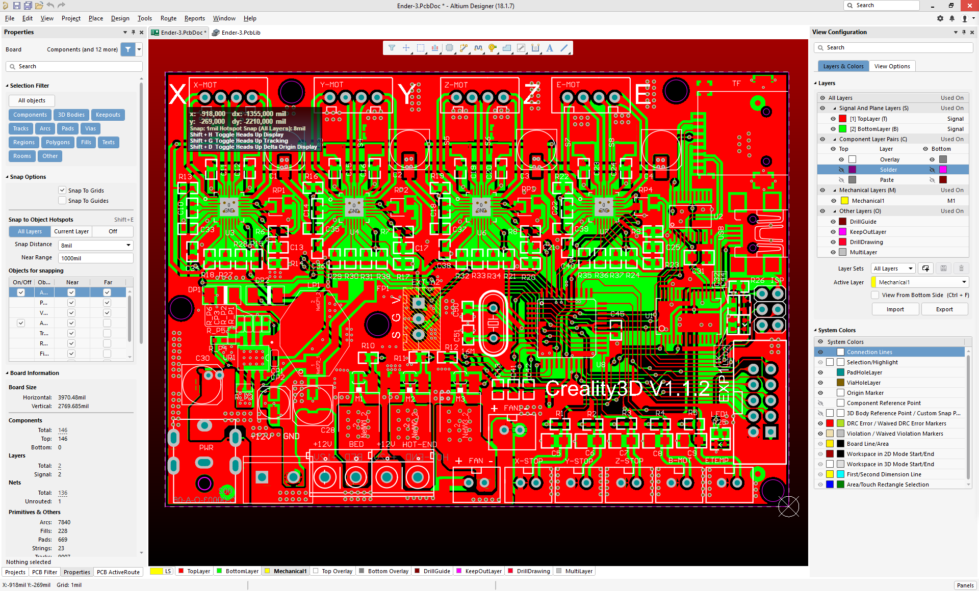
I opened the files in a trial version of Altium and exported the top and bottom layers as pngs. I made a pull request for them: #14
Additionally, I've gone through the exercise of tracing the lines for the 6-pin ISP connector and the 10-pin LCD connector. I know what pins they are connected to (and the Arduino pins, should someone need to reference them in source code) as well as what they are logically used for (credit: https://github.com/RudolphRiedel/CR-10_wiring). I don't exactly know how/where is the best place to document those. If anyone has any suggestions, please let me know.
from ender-3.
 Gazza-USA
commented on July 16, 2024
Gazza-USA
commented on July 16, 2024
Guys, if you point me to the files I will take a look too. I professionally use Altium and can take a look at the netlist etc. If the native file is in another format (PADS, Allegro) send me that too. If anyone has the schematics in any form too that would help.
from ender-3.
Gazza-USA
commented on July 16, 2024
A friend asked me something about the FETs on board and so I had a closer look.
First is that these are named REP30N06LE in the board and the BOM while it is likely that these are RFP30N06LE.Okay, we have an external FET for the bed and the fan does not draw much power which leaves the hot-end FET sending some amperes thru the board.
Looking at the GND from the board though I find no solid connection between the three FETs and the GND connector on the board from the PSU.
The same applies to the stepper drivers.
Yeah, I found exactly the errors you did. They obviously don’t know how to use the tools properly as there are stacks of pads and component pads that are incorrectly defined. Via stitching would solve the GND break and sorting out the polygon pour order would fix other things. I did a cleanup myself for fun. It looks like some things have been added after the schematics too like a resistor for an LED. This is all just physical copper with no nets so it generates DRCs.
from ender-3.
RudolphRiedel
commented on July 16, 2024
Have you even read the thread?
It's been 2 1/2 months now and there still is no schematic for the control-board from Creality.
It is like they do not even have a schematic.
Maybe this is annother contract job like they told us the modification of the software was.
And that the original .PCB is in a 20 year old Protel format without almost no 3D models is rather strange, together with apprentice-level flaws like the grouping of C41/C42/C43.
I am tempted to re-work the board but so far there has been no sign of apreciation of what is going on here whatsoever from Creality, so far this is a dead repository.
from ender-3.
MachineryEnchantress
commented on July 16, 2024
Sorry I've been working on getting the CAD files uploaded. What can I get you from them?
from ender-3.
RudolphRiedel
commented on July 16, 2024
What can I get you from them?
Well, the whole project directory they are actually using for development would be nice.
And as the same PCB is used at least in the CR-10 that is rather unlikely to have "Ender-3" in any of the files.
I even doubt that the actual board file is named xxx.PCB since that would mean the board is beeing developed with software that is 20 years old.
So, the real files would be a kicker, board.PcbDoc, board.SchDoc and board.PrjPcb at the very least if the board is indeed designed with Altium Designer. Plus board.PrjPcbStructure and the xxx.PcbLib, xxx.SchLib.
Edit: actually the project directory should contain several boardXXX.SchDoc and not only a single one.
Also a board.PrjPcbVariants should be included as at least there is one connector replaced with a capacitor specifically for the Ender-3.
If that is for some reason not possible at the very least a Ender-3.SCH would be nice and of course the latest version of the Ender-3.PCB as this one was outdated even before it was released here.
from ender-3.
MachineryEnchantress
commented on July 16, 2024
Does anyone want to ask for something without calling the people being asked liars or making accusations of duplicity in the same post?
from ender-3.
RudyFiero
commented on July 16, 2024
Could we please get the current documentation for board. The Ender 3 I have has a pcb revision of 1.1.3.
Personally I want the schematic. I have no intention of ever producing a replacement board. I want accurate information so that I make proper decisions on firmware upgrades.
from ender-3.
DuncanAmos
commented on July 16, 2024
In an ideal world, what we really need from Creality is Board files,
Schematics, Mechanicals and Code for every version that has made it into
the sales chain and could be in the hands of a customer.
Whether that is ever going to be achievable is somewhat doubtful, but I
live in hope...
…On Sat, 15 Sep 2018, 15:14 Rudy, ***@***.***> wrote:
Could we please get the current documentation for board. The Ender 3 I
have has a pcb revision of 1.1.3.
Personally I want the schematic. I have no intention of ever producing a
replacement board. I want accurate information so that I make proper
decisions on firmware upgrades.
—
You are receiving this because you commented.
Reply to this email directly, view it on GitHub
<#2 (comment)>,
or mute the thread
<https://github.com/notifications/unsubscribe-auth/AXX1IGzxZw_D5p-V7LL5K4ppSEs_WzcKks5ubP1BgaJpZM4VBpFN>
.
from ender-3.
RudolphRiedel
commented on July 16, 2024
Does anyone want to ask for something without calling the people being asked liars
As this is clearly is addressed to me, please point out where I did that.
That is just your interpretation of what I wrote.
I was throwing around some facts and assumptions based on these facts.
I did not write that Creality is trying to lie to us here or they acting in bad faith.
The renaming of the .PCB to Ender-3.PCB is easily explained by the fact that this is the Ender-3 repository and this was done in order to have everything named alike.
All the files could have chinese names, again I am not saying that would be bad, this is just a possible explanation.
I saw no statement before that Creality is developing this in-house so the assumption that this is a contract work was only made to explain why after 2 1/2 months the schematic is still missing.
And this would be a totally legit explanation.
I am glad that this assumption is not correct as this means Creality must have the schematics.
or making accusations of duplicity in the same post?
And I do not get how you come to this conclusion either.
Please point it out to me.
All I see is that I pointed out the fact that the data is not complete without assesment as of which this is the case. And I offered help with this by listing all the extensions of the files that should be in the directory and that are now missing.
The Ender-3 is sold with the V1.1.3 board but the data released is for the V1.1.2 board - it says so in the silkscreen. Again, nothing but a fact.
If it helps they are using Altium Designer 6.9
Yes, this helps since in that case it really is not a Protel file and I was wrong in assuming it is.
I just checked the Ender-3.PCB with a hex-viewer and found the string "PCB 6.0 Binary File".
While older and a few things have changed since this, this still is a Altium Designer file and at least files saved with AD17 still have that 6.0 tag.
I was wrong and I admit that.
However, you could have pointed out that I am wrong two months ago.
And when I right-click a pcb file and select save-as, only PCB versions 3.0 and 4.0 get named .PCB while 5.0 and current is named .PcbDoc.
Sure, it is totally possible that the engineer uses old file extensions, really old file extensions.
But I should be allowed to find that strange.
And me finding that strange does not mean he is doing it wrong.
Please just let him .zip the directory he is working with.
Maybe make a copy and clean out a few sub-directories before that like "_Previews", "History" and "Project Outputs...".
On August 16 I offered to point out the needed files if you provide a screenshot of the directory.
I am really trying to be helpfull here.
And just look at the timelime and the posts, if that does not reflect patience I do not know what would.
from ender-3.
RudyFiero
commented on July 16, 2024
"Does anyone want to ask for something without calling the people being asked liars"
As this is clearly is addressed to me, please point out where I did that.
It was not addressed to you. Not specifically I would think. Yes you have been coming across as ... not someone I would want to know.
If she isn't getting the kind of material that would be useful then I think it is because whoever she is dealing with is either not being as helpful, or they have been directed to not provide very useful information.
This was my comment from a previous post. And based on the information I have seen, I do wonder if the intent is to appear to be open source but to limit the usefulness of the presented material.
My thought is that if someone wanted to use the design information to copy, and produce a knock-off product, that it would not work. I don't know if that is the intent, but it would be perfectly reasonable to expect that. Even if someone wanted to produce a copied product I doubt if it would be successful. I don't believe that kind of startup could compete with Creality, on price, and considering reputation.
If an individual wanted to use the design to make their own printer I would think it would end up costing more than to just buy the Creality product. The idea that we could save money by doing it yourself often doesn't add up, but I'm sure there are some that think that.
I think that having the files open source, accurate information, helps enthusiasts to push the design a little further. They are not a threat to a company like Creality, but a source for potential advancement and should be encouraged.
I understand that there are translation issues but I would be surprised that is the real problem.But I wonder why accurate and current version information has not been released. Even if it were older versions, but complete and accurate, I would have less doubt.
from ender-3.
MachineryEnchantress
commented on July 16, 2024
Ok nevermind then. It's compliant. That's what you get.
from ender-3.
 wjsteele
commented on July 16, 2024
wjsteele
commented on July 16, 2024
"However, you could have pointed out that I am wrong two months ago." - @RudolphRiedel
How could she have done that... she said herself she has no knowledge of the toolchain. You're so smart, you should have figured that out yourself way before she should have been able to. It's attitudes like that which are the problem here.
All anyone has to do is ask nicely for what it is they are looking for. Instead you cop an attitude like you're superior in some way.
And I agree with RudyFiero, you're not someone I'd want to know personally as well with that attitude, however, I have to disagree with him about the rest of his comment. The assertion that they are just trying to appear to be open source is just a damn stupid thing to say... that's just as accusatory as what RudolphRiedel said. That doesn't help the situation one bit... instead, just as it happened, it drives them away from trying to cooperate with you.
Jeesh, guys, get a clue here... OSHW is entirely new to the Chinese... they work on a totally different philosophy, and despite what you think... you can't change their ways overnight. They have no concept of some of the things we do, or even an understanding of why we do them. Don't go off on me about "Well they should..."... it's not going to happen... especially overnight. We both need to work together to move forward.
She asked what she could get you to help you out... and you both blew it off and instead continued with your own diatribes about what you want and made accusations based on (false) assumptions.
How about a simple, "Hey, @sexycyborg, how about if we start off asking them for the schematics for the 1.1.3 boards? Those would be the most helpful right now." That's simple enough and friendly... and then we can work it up to more details later.
from ender-3.
DuncanAmos
commented on July 16, 2024
I agree with Wm Steele, on all points.
To traditional manufacturers, with a traditional business model, Open
Source makes absolutely no sense whatsoever - you put in, and pay for, a
huge number of design hours and then give your designs away for free???
That is a difficult concept to grasp anywhere, and much more so in a
country as traditional as China.
Naomi's article in Make Magazine #61 tells how difficult it has been to get
Open Source even considered in China - maybe those who believe it's easy
should read that...
Yes, we'd like the schematics for the 1.1.3 boards but let's remember to
ask nicely and not demand them...
Naomi is doing the best she can, let's support her and try and understand
the problems she's up against...
On Sun, 16 Sep 2018, 03:00 Wm Steele, ***@***.***> wrote:
*"However, you could have pointed out that I am wrong two months ago."* -
@RudolphRiedel <https://github.com/RudolphRiedel>
How could she have done that... she said herself she has no knowledge of
the toolchain. You're so smart, you should have figured that out yourself
way before she should have been able to. It's attitudes like that which are
the problem here.
All anyone has to do is ask nicely for what it is they are looking for.
Instead you cop an attitude like you're superior in some way.
And I agree with RudyFiero, you're not someone I'd want to know personally
as well with that attitude, however, I have to disagree with him about the
rest of his comment. The assertion that they are just trying to appear to
be open source is just a damn stupid thing to say... that's just as
accusatory as what RudolphRiedel said. That doesn't help the situation one
bit... instead, just as it happened, it drives them away from trying to
cooperate with you.
Jeesh, guys, get a clue here... OSHW is entirely new to the Chinese...
they work on a totally different philosophy, and despite what you think...
you can't change their ways overnight. They have no concept of some of the
things we do, or even an understanding of why we do them. Don't go off on
me about "Well they should..."... it's not going to happen... especially
overnight. We both need to work together to move forward.
She asked what she could get you to help you out... and you both blew it
off and instead continued with your own diatribes about what you want and
made accusations based on (false) assumptions.
How about a simple, "Hey, @sexycyborg <https://github.com/sexycyborg>,
how about if we start off asking them for the schematics for the 1.1.3
boards? Those would be the most helpful right now." That's simple enough
and friendly... and then we can work it up to more details later.
—
You are receiving this because you commented.
Reply to this email directly, view it on GitHub
<#2 (comment)>,
or mute the thread
<https://github.com/notifications/unsubscribe-auth/AXX1IDBEBUp-XKjCgCjDeN06b9Z72UEnks5ubaKUgaJpZM4VBpFN>
.
On 16 Sep 2018 03:00, "Wm Steele" <[email protected]> wrote:
*"However, you could have pointed out that I am wrong two months ago."* -
@RudolphRiedel <https://github.com/RudolphRiedel>
How could she have done that... she said herself she has no knowledge of
the toolchain. You're so smart, you should have figured that out yourself
way before she should have been able to. It's attitudes like that which are
the problem here.
All anyone has to do is ask nicely for what it is they are looking for.
Instead you cop an attitude like you're superior in some way.
And I agree with RudyFiero, you're not someone I'd want to know personally
as well with that attitude, however, I have to disagree with him about the
rest of his comment. The assertion that they are just trying to appear to
be open source is just a damn stupid thing to say... that's just as
accusatory as what RudolphRiedel said. That doesn't help the situation one
bit... instead, just as it happened, it drives them away from trying to
cooperate with you.
Jeesh, guys, get a clue here... OSHW is entirely new to the Chinese... they
work on a totally different philosophy, and despite what you think... you
can't change their ways overnight. They have no concept of some of the
things we do, or even an understanding of why we do them. Don't go off on
me about "Well they should..."... it's not going to happen... especially
overnight. We both need to work together to move forward.
She asked what she could get you to help you out... and you both blew it
off and instead continued with your own diatribes about what you want and
made accusations based on (false) assumptions.
How about a simple, "Hey, @sexycyborg <https://github.com/sexycyborg>, how
about if we start off asking them for the schematics for the 1.1.3 boards?
Those would be the most helpful right now." That's simple enough and
friendly... and then we can work it up to more details later.
—
You are receiving this because you commented.
Reply to this email directly, view it on GitHub
<#2 (comment)>,
or mute the thread
<https://github.com/notifications/unsubscribe-auth/AXX1IDBEBUp-XKjCgCjDeN06b9Z72UEnks5ubaKUgaJpZM4VBpFN>
.
from ender-3.
RudolphRiedel
commented on July 16, 2024
Stop interpreting plain text to the point of assuming what others think.
All you do is project an agenda upon me that I do not have.
Read what I wrote, do not try to apply what you think of it to what I might be thinking
Instead you cop an attitude like you're superior in some way.
I have no idea where you are getting that from.
All I did was to provide information that has been said is missing.
Anyone working with Altium Designer could have provided that information, anyone.
All anyone has to do is ask nicely for what it is they are looking for.
Please do.
from ender-3.
Gazza-USA
commented on July 16, 2024
It would be kind of Creality to put the Ender 3 V1.1.3 (or V1.1.4 if available) PCB files up for us as per OSHW agreement. It would help them tremendously if we had the schematics as we could ensure that all the files get updated. I’m willing to do this (I consult and do high speed electronics design daily so this is an easy project for me). I’ll update the design to clean up any potential issues which would make the design both better and possibly cheaper. The benefit to Creality is that they would have an improved design that they can use along with the ability for their users to upgrade the controller board. This translates into Creality’s reputation and sales volume going up. Win-win.
Otherwise, I may reverse engineer what we have to move forward.
I use Altium Designer (all flavours). Can translate Orcad etc if needed.
from ender-3.
RudolphRiedel
commented on July 16, 2024
I am waiting for an Ender-3 actually, maybe I can determine then what the difference to the 1.1.2 board is.
from ender-3.
DuncanAmos
commented on July 16, 2024
As far as I'm aware (and I'm certainly no expert), the current release is
v1.1.3.
Let's not muddy the waters further by asking for something that has yet to
be released for sale.
…On Sun, 16 Sep 2018, 23:21 Gazza-USA, ***@***.***> wrote:
Just to let you all know the V1.1.2 board is definitely not usable. On the
V1.1.2, the USB pins come from the HC541 buffer but there's no input. Also
the SD card pins are not fully defined or connected. So with that said it
would be kind of Creality to put the Ender 3 V1.1.3 (or V1.1.4 if
available) PCB files up for us as per OSHW agreement.
—
You are receiving this because you commented.
Reply to this email directly, view it on GitHub
<#2 (comment)>,
or mute the thread
<https://github.com/notifications/unsubscribe-auth/AXX1IP0jl6fIoS5Xp1bpGrdUTFrb9rhIks5ubsDSgaJpZM4VBpFN>
.
from ender-3.
Gazza-USA
commented on July 16, 2024
I corrected my comment. You guys are too quick!! The v1.1.2 might be OK. I don’t have schematics to double check. However I did fix a load of issues on the PCB like badly defined holes and copper voids/no connects. This is local to me only at the moment.
from ender-3.
 sl1pkn07
commented on July 16, 2024
sl1pkn07
commented on July 16, 2024
anyone can translate all pcb to kicad format? is more opensource compiant
greetings
from ender-3.
adamtegen
commented on July 16, 2024
If there isn't an automated way, if I had an exported PDF/ screenshot, I
could start working on it in my spare time.
For what it's worth, my guess is it will be somewhat similar to this for
the CR-10
https://github.com/RudolphRiedel/CR-10_wiring/blob/master/CR-10_Wiring.pdf
…On Mon, Sep 17, 2018 at 10:17 AM Gustavo Alvarez ***@***.***> wrote:
anyone can translate all pcb to kicad format? is more opensource compiant
greetings
—
You are receiving this because you commented.
Reply to this email directly, view it on GitHub
<#2 (comment)>,
or mute the thread
<https://github.com/notifications/unsubscribe-auth/ABpbKOXfEte0UIJD1-OknM97k7w53gN8ks5ub70QgaJpZM4VBpFN>
.
from ender-3.
sl1pkn07
commented on July 16, 2024
¿Alguien puede traducir todo el pcb al formato kicad?
¿Has probado el convertidor mencionado anteriormente?
Con el formato .PcbDoc en AD17 que adjunté el 6 de julio?
sorry, i'm linux only user
greetings
from ender-3.
RudolphRiedel
commented on July 16, 2024
Try this: https://github.com/thesourcerer8/altium2kicad
from ender-3.
sl1pkn07
commented on July 16, 2024
┌─┤[$]|[sl1pkn07]|[sL1pKn07]|[~/aplicaciones/Creality_Ender_3/Ender-3/Ender-3 PCB/PCB 5.0 Binary File]|
└───╼  ../../../altium2kicad/unpack.pl
Loading Ender-3.PcbDoc

Done.
┌─┤[$]|[sl1pkn07]|[sL1pKn07]|[~/aplicaciones/Creality_Ender_3/Ender-3/Ender-3 PCB/PCB 5.0 Binary File]|
└───╼  ../../../altium2kicad/convertpcb.pl
No unpacked .PcbDoc documents found. Trying to unpack it:
Loading Ender-3.PcbDoc

Done.
There were no unpacked PcbDoc files found.
from ender-3.
RudolphRiedel
commented on July 16, 2024
Use the file I posted above:
https://github.com/Creality3DPrinting/Ender-3/files/2171524/Ender-3_PcbDoc.zip
This one is saved with AD17.
I just used the online service in the link and received a file that is supposedly in KiCad format.
I can not test it because I do not have KiCad installed.
from ender-3.
sl1pkn07
commented on July 16, 2024
└───╼  ../altium2kicad/convertpcb.pl
Handling Ender-3-PcbDoc/Root Entry/Board6/Data.dat
ASCII-Ender-3-PcbDoc.PcbDoc exists?
Writing to Ender-3-PcbDoc/Root Entry/Board6/Data.dat.txt
Writing to Ender-3-PcbDoc/Root Entry/Models/Data.dat.txt
Writing to Ender-3-PcbDoc/Root Entry/UniqueIDPrimitiveInformation/Data.dat.txt
Writing to Ender-3-PcbDoc/Root Entry/Rules6/Data.dat.txt
Writing to Ender-3-PcbDoc/Root Entry/Classes6/Data.dat.txt
Writing PCB to Ender-3-PcbDoc.kicad_pcb
Writing to Ender-3-PcbDoc/Root Entry/Nets6/Data.dat.txt
Writing to Ender-3-PcbDoc/Root Entry/Components6/Data.dat.txt
Pads6...
WARNING: Currently only the PadMode (Size and Shape) Simple is supported, Top-Middle-Bottom is not supported by KiCad because KiCad uses the same Shape and Size on all layers.
Writing to Ender-3-PcbDoc/Root Entry/ComponentBodies6/Data.dat.txt
NOT FOUND: hx254-3tl_y.wrl
Writing to Ender-3-PcbDoc/Root Entry/ShapeBasedComponentBodies6/Data.dat.txt
Writing to Ender-3-PcbDoc/Root Entry/Components6/Data.dat.txt
Where did the model come from? componentid: 145
Writing to Ender-3-PcbDoc/Root Entry/Arcs6/Data.dat.txt
Writing to Ender-3-PcbDoc/Root Entry/Vias6/Data.dat.txt
Writing to Ender-3-PcbDoc/Root Entry/Polygons6/Data.dat.txt
Writing to Ender-3-PcbDoc/Root Entry/Tracks6/Data.dat.txt
Writing to Ender-3-PcbDoc/Root Entry/FileVersionInfo/Data.dat.txt
Writing to Ender-3-PcbDoc/Root Entry/Fills6/Data.dat.txt
Writing to Ender-3-PcbDoc/Root Entry/Regions6/Data.dat.txt
Texts6...

from ender-3.
RudolphRiedel
commented on July 16, 2024
I opened the file I got from the converter with KiCad and it came out totally broken for me as well.
Most of the footprints are missing.
from ender-3.
RudolphRiedel
commented on July 16, 2024
I have an Ender-3 now. :-)
What surprised me the most was how quiet it is compared to how my CR-10 was.
I can confirm it has been delivered with a control board that has "V1.1.3" written on it.
Please! Please update the controller board information to reflect this version.
And please , please add the rest of the missing files. Like the schematic for the controller-board, a schematic for the whole setup with all components and a list of all the components used like the stepper-motors, the fans, the heater cartridge, the heat-bed, the end-stops, the display.
Edit: my mistake, I found the Ender-3 BOM.XLS in "Ender-3 Mechanical" now which does not only list purely mechanical parts but practically everything, sweet.
Almost everything I listed already is specified with sufficent detail or simply do not need much detail.
As the "lcd Knob" or the "limit switch" or the "LCD".
Going thru the list, I have not received a "shovel" with my Ender-3. :-)
But since there is no spatula in the list... :-)
On August 20th I wrote: "Okay, we have an external FET".
That is not true for the Ender-3, but a feature of the CR-10 which uses the same controller-board.
This is not a complaint (although I wish it had an external FET for the bed) but something I got wrong beforehand and that I wanted to address.
from ender-3.
 Deneteus
commented on July 16, 2024
Deneteus
commented on July 16, 2024
I came here looking for the wirings schematic and I also wanted to confirm the endstop switch connecter wiring as they used 3 pin to 2 pin adapters and I would like to add the end stop LEDs back on the board.
I hope any future versions have a connector that can be specifically used for Auto Bed leveling, either Capacitive, Inductive, IR, or BLTouch.
Thanks for posting this @sexycyborg!
from ender-3.
RudolphRiedel
commented on July 16, 2024
I hope any future versions have a connector that can be specifically used for Auto Bed leveling,
either Capacitive, Inductive, IR, or BLTouch.
There kind of is. See https://github.com/RudolphRiedel/CR-10_wiring/blob/master/CR-10_Wiring.pdf
The header EXT-A2 appeared on the V1.1.2 versions of the board which were delivered at least with later revisions of the CR-10.
The header makes the only IO pin available that is left on the M1284P.
I believe it was used for a filament runout-sensor.
However, the boards that are delivered with the Ender-3 do have a capacitor populated instead of the header so you can not directly use it:

But it is still possible to solder a wire to it and this is way better than soldering wires directly to the controller-pins.
One could also move the capacitor and free the pads for the connector but this might defeat the purpose of that capacitor.
from ender-3.
RudolphRiedel
commented on July 16, 2024
Okay, it has been four weeks with no reaction again.
I have been ignored here with no clarifications on the attacks towards me and my tries to get in touch personally to sort out the issue of the missing files have been ignored as well.
And nothing has been added to the repository, not even the files provided in the threads.
I really do not like this but I feel that someone has to stand up and protest and I see no one else doing it.
If this here continues I will take it to a higher authority.
And this sat here for 20+ Minutes in the text-box waiting for me to hit the "Comment" button, still feels bad but I kind of have to. sorry.
from ender-3.
wjsteele
commented on July 16, 2024
Hmmm... A higher authority? For something that is purely voluntary?
Back to the point... What are you asking for? Your previous comment looked like you were happy and it wasn't 40 days ago.
from ender-3.
DuncanAmos
commented on July 16, 2024
The capacitor is there to provide additional smoothing to the +5V rail,
close to the processor - primarily to reduce the inconsistencies in the
thermistor readings.
It can certainly be relocated to free-up the EXT-A2 pads for the connector
to be fitted. The right-hand end (as shown in the photo) of the thermal
fuse (FP1) can be used for the +5V and the Gnd connection can be achieved
by scraping away some of the solder resist on the ground plane that is
adjacent to it.
…On Fri, 12 Oct 2018, 17:30 RudolphRiedel, ***@***.***> wrote:
I hope any future versions have a connector that can be specifically used
for Auto Bed leveling,
either Capacitive, Inductive, IR, or BLTouch.
There kind of is. See
https://github.com/RudolphRiedel/CR-10_wiring/blob/master/CR-10_Wiring.pdf
The header EXT-A2 appeared on the V1.1.2 versions of the board which were
delivered at least with later revisions of the CR-10.
The header makes the only IO pin available that is left on the M1284PA.
I believe it was used for a filament runout-sensor.
However, the boards that are delivered with the Ender-3 do have a
capacitor populated instead of the header so you can not directly use it:
[image: grafik]
<https://user-images.githubusercontent.com/31180093/46878597-00201280-ce44-11e8-958e-1d8c44df6c51.png>
But it is still possible to solder a wire to it and this is way better
than soldering wires directly to the controller-pins.
One could also move the capacitor and free the pads for the connector but
this might defeat the purpose of that capacitor.
—
You are receiving this because you commented.
Reply to this email directly, view it on GitHub
<#2 (comment)>,
or mute the thread
<https://github.com/notifications/unsubscribe-auth/AXX1IN-gYUhj_JGs0kcuC1zISsTM8dTQks5ukLV8gaJpZM4VBpFN>
.
from ender-3.
RudolphRiedel
commented on July 16, 2024
and neither is there any obligation on Naomi, or anyone else, to provide information on here.
It is entirely voluntary...
They made it an obligation themselves by putting a certificate onto it.
I am just asking them to live up to the promise they made.
If this is everything, okay, fine, but please give up the OSHWA certificate then.
And lets not forget that the design the controller board is based on was released under GPL.
So there you have annother obligation to release the files.
What are you asking for? Your previous comment looked like you were happy and it wasn't 40 days ago.
I was just trying to be patient and not pushing.
I am almost done with the sweet-talk, I tried to solve this in private mail and have been ignored.
I offered help here and was ignored.
I am asking for the same thing as mentioned several times in this thread and as I wrote first on fourth of July.
Please release the schematic for the controller board.
And as it turned out the version of the Ender-3.PCB file for the 1.1.3 revision of that board since that is the board that is delivered with the Ender-3.
In addition, what also can be considered missing is a schematic for the machine as a whole.
This whole thing here is remarkable, much respect for going as far and putting the information here!!
But I strongly feel that this still has to go a little further to fullfill the promise that has been made.
And I would not feel like this if I was not convinced that these are great machines. I do own a CR-10 for almost a year now. I bought an Ender-3 for my company and subsequently pratically sold at least three more so far even while this is going on here. The most difficult thing for me is to not just buy an Ender-3 to be placed next to my CR-10.
Although I initially felt disapointed when I found out that the CR-10 is using a controller board that is derived from an open source design under GPL but without providing information.
Much like I would at this point not buy anything from MakerBase.
But I am here because I have hope that this still can be resolved.
from ender-3.
DuncanAmos
commented on July 16, 2024
I would suggest that you direct your comments, certainly those about
obligations under OSHWA and GPL, to Creality themselves - not to those who
are doing this in their own time and who have no direct connection with the
company.
Your comments are counterproductive when it comes to building a
relationship and fostering trust.
For Creality, and for China in general, Open Source anything is a
completely alien concept, as I have stated previously.
Why not be grateful you've got a good printer at a good price and wait for
the rest to happen - without continually winging, complaining and making
threats?
If you were really that desperate for a schematic of the Ender 3 mainboard,
you would have reverse engineered it from the PCB by now, instead of
behaving like a petulant child.
You wrote "The most difficult thing for me is to not just buy an Ender-3 to
be placed next to my CR-10" - why???
You've "bought an Ender-3 for [your] company and subsequently practically
sold at least three more so far".
You seem more than happy with placing the product in the hands of others
(with or without schematics), but that's not good enough for you...
Hypocrisy...
…On Sun, 14 Oct 2018, 13:29 RudolphRiedel, ***@***.***> wrote:
and neither is there any obligation on Naomi, or anyone else, to provide
information on here.
It is entirely voluntary...
They made it an obligation themselves by putting a certificate onto it.
I am just asking them to live up to the promise they made.
If this is everything, okay, fine, but please give up the OSHWA
certificate then.
And lets not forget that the design the controller board is based on was
released under GPL.
So there you have annother obligation to release the files.
What are you asking for? Your previous comment looked like you were happy
and it wasn't 40 days ago.
I was just trying to be patient and not pushing.
I am almost done with the sweet-talk, I tried to solve this in private
mail and have been ignored.
I offered help here and was ignored.
I am asking for the same thing as mentioned several times in this thread
and as I wrote first on fourth of July.
Please release the schematic for the controller board.
And as it turned out the version of the Ender-3.PCB file for the 1.1.3
revision of that board since that is the board that is delivered with the
Ender-3.
In addition, what also can be considered missing is a schematic for the
machine as a whole.
This whole thing here is remarkable, much respect for going as far and
putting the information here!!
But I strongly feel that this still has to go a little further to fullfill
the promise that has been made.
And I would not feel like this if I was not convinced that these are great
machines. I do own a CR-10 for almost a year now. I bought an Ender-3 for
my company and subsequently pratically sold at least three more so far even
while this is going on here. The most difficult thing for me is to not just
buy an Ender-3 to be placed next to my CR-10.
Although I initially felt disapointed when I found out that the CR-10 is
using a controller board that is derived from an open source design under
GPL but without providing information.
Much like I would at this point not buy anything from MakerBase.
But I am here because I have hope that this still can be resolved.
—
You are receiving this because you commented.
Reply to this email directly, view it on GitHub
<#2 (comment)>,
or mute the thread
<https://github.com/notifications/unsubscribe-auth/AXX1IFazapJzg0jAqBCnD0oBMk7ybJr9ks5ukyAOgaJpZM4VBpFN>
.
from ender-3.
RudolphRiedel
commented on July 16, 2024
I would suggest that you direct your comments, certainly those about obligations under OSHWA and GPL, to Creality themselves
This is the official repository for Creality3DPrinting for the Ender-3, how is this not directly adressing them?
- not to those who are doing this in their own time and who have no direct connection with the company.
I am only adressing this to the official company liason of Creality3D who is working directly with the Engineer at Creality3D who is resposible for the design of the controller-board.
I offered help and was ignored, I offered to discuss this in private and was ignored.
Why not be grateful you've got a good printer at a good price and wait for the rest to happen
Because it has been over three months now and we are not talking about files that need to be created first,
I am not asking for something like a port to EAGLE or KiCAD which would require work and therefore time., this would be silly.
I am only asking to release the files Creality3D already has and I will happily convert the Altium files to .pdf for everyone without Altium.
It's not like I am posting every three days to ask for the schematic.
If you were really that desperate for a schematic of the Ender 3 mainboard, you would have reverse engineered it from the PCB by now
If the issue would have been made clear from the start instead of dodging it, I would have reverse-engineered it by now. But I simply saw no reason to further push the schematic I already started.
You can put your head into as much sand as you like and apologize for them as much as you want and keep attacking me personally. But to what extend did that help so far?
from ender-3.
DuncanAmos
commented on July 16, 2024
I most certainly do not have my head in the sand and neither am I defending
Creality or labouring under any illusions that I have helped the situation
in any way.
I am, however, very aware of the cultural differences that make the whole
Open Source thinking difficult to accept (as Naomi has previously
mentioned) and the negative effect that continual moaning has in a culture
that is bound by respect.
As someone said in a post three months ago, "they [Creality] no not "need"
to supply anything and we can consider us lucky that they supplied as much
as they have now." and "And for what purpose do you really "need" the
files? Do you plan to build your own improved PCB?"
That poster was making the point that the files were a plus and that we
should be grateful that we have anything at all.
Maybe you should contact that person and tell them how wrong they were. How
Creality need to be reported to a "higher authority" for not providing
exactly what you require?
It should be easy enough to contact them, the poster's screen name was
RudolphRiedel...
…On Sun, 14 Oct 2018, 15:46 RudolphRiedel, ***@***.***> wrote:
I would suggest that you direct your comments, certainly those about
obligations under OSHWA and GPL, to Creality themselves
This is the official repository for Creality3DPrinting for the Ender-3,
how is this not directly adressing them?
- not to those who are doing this in their own time and who have no
direct connection with the company.
I am only adressing this to the official company liason of Creality3D who
is working directly with the Engineer at Creality3D who is resposible for
the design of the controller-board.
I offered help and was ignored, I offered to discuss this in private and
was ignored.
Why not be grateful you've got a good printer at a good price and wait for
the rest to happen
Because it has been over three months now and we are not talking about
files that need to be created first,
I am *not* asking for something like a port to EAGLE or KiCAD which would
require work and therefore time., this would be silly.
I am only asking to release the files Creality3D already has and I will
happily convert the Altium files to .pdf for everyone without Altium.
It's not like I am posting every three days to ask for the schematic.
If you were really that desperate for a schematic of the Ender 3
mainboard, you would have reverse engineered it from the PCB by now
If the issue would have been made clear from the start instead of dodging
it, I would have reverse-engineered it by now. But I simply saw no reason
to further push the schematic I already started.
You can put your head into as much sand as you like and apologize for them
as much as you want and keep attacking me personally. But to what extend
did that help so far?
—
You are receiving this because you commented.
Reply to this email directly, view it on GitHub
<#2 (comment)>,
or mute the thread
<https://github.com/notifications/unsubscribe-auth/AXX1IEbvka1faGR_IFJV7D5f4X-fhmmuks5uk0AngaJpZM4VBpFN>
.
from ender-3.
RudolphRiedel
commented on July 16, 2024
As someone said in a post three months ago, "they [Creality] no not "need" to supply anything
Sure, take that out of context, no problem at all.
And I am very gratefull for what we got so far and I have much respect for what they have done, especially for a chinese company!
I am also well aware that they released the software for all their printers on their hompage now, very impressive: https://www.creality3d.cn/download/firmware_c0001
from ender-3.
 rickyrockrat
commented on July 16, 2024
rickyrockrat
commented on July 16, 2024
Gerbers (with a gerbv project file) are here for V1.1.2, and a fix for V1.1.3:
https://github.com/rickyrockrat/Ender-3/tree/master/V1.1.2Gerber
from ender-3.
sl1pkn07
commented on July 16, 2024
then, if i remove the capacitor and put in it a jst pin header, can use as filament sensor (or any sensor, like bltouch) like say in the motherboard diagram?
from ender-3.
RudolphRiedel
commented on July 16, 2024
Sure, like I explained a litte further above.
The header connects to the only unused I/O pin of the M1284P.
from ender-3.
RudyFiero
commented on July 16, 2024
If you remove the capacitor from that spot (in order to use the header) you should be putting the capacitor back into the circuit in an equivalent position. They put it there to fix a problem. Just removing it may cause operational issues.
from ender-3.
DuncanAmos
commented on July 16, 2024
I suspect (and it's only a guess) that one difference between v1.1.2 and
v1.1.3 may have been to fix a ground track right at the edge of the board
(left side, viewed from above, I think) that was often broken when the
individual boards were separated from the panel.
That was something that caused all sorts of issues.
…On Fri, 1 Feb 2019, 16:59 RudolphRiedel, ***@***.***> wrote:
Have you figured out what the difference is between the V1.1.2 and the
V1.1.3?
I have both boards on my desk and have not noticed anything else than that
EXT-A2 is populated with a capacitor on the V1.1.3 instead of the 3-pin
header.
This alone should not be enough for a new board revision, this is merely a
change in the BOM.
Also, I forked the Melzi 1.1.2 repository, threw away the "schematic" that
does not match the V1.1.2 board and put all the files in it that I still
miss in the Ender-3 repository:
https://github.com/RudolphRiedel/CR10-Melzi-1.1.2/tree/master/Circuit%20diagram/Motherboard
I also went a step further and started correcting a few bugs with the
original .PCB.
Nothing functional though, it still is a V1.1.2, only with less broken
data.
—
You are receiving this because you commented.
Reply to this email directly, view it on GitHub
<#2 (comment)>,
or mute the thread
<https://github.com/notifications/unsubscribe-auth/AXX1IJ8h3cEMP85vLVnlQgGOpvdhQqSsks5vJGRggaJpZM4VBpFN>
.
from ender-3.
RudolphRiedel
commented on July 16, 2024
I do not see it.
I have both boards here and from above there is no difference.

There is a difference on the bottom though.


There is very small copper-bridge at the bottom near the left hole.
And this tiny bridge that hardly counts as a trace is gone on the V1.1.3 board that I have.,
This is not an improvement though, it makes the layout worse.
And it merely looks like an accident or happened by chance as this bridge is so small that different batches of the V1.1.2 could not have it while different batches of V1.1.3 have it.
A deliberate change for the better would have been to make this significantly wider.
from ender-3.
 LongLiveCHIEF
commented on July 16, 2024
LongLiveCHIEF
commented on July 16, 2024
I'm having a problem where my hotend heats up immediately on powerup. I pulled the board and i'm just looking to replace the fets that are bad. I have tons in stock, but can't find the datasheet for the part number (KGA7114), and it would be nice to know the specs so i know if i have something in my inventory I can swap in for a quick fix.
from ender-3.
RudolphRiedel
commented on July 16, 2024
You found the "wrong" thread. :-)
#26
The problem is to identify which FETs are really on the board, especially since the heatsink is glued to them.
If these are really RFP30N06LE it should not be that hard to find a replacement.
It is not that difficult to beat 47mR at 5V.
Edit: and I just checked that now, I definately would not go for the IRF522.
from ender-3.
LongLiveCHIEF
commented on July 16, 2024
I pulled the heatsink off and tested them. It's the middle one.
from ender-3.
LongLiveCHIEF
commented on July 16, 2024
Looks like IRLR3114 should work, but I got a MKS Gen L coming anyways so... /shrug
from ender-3.
Deneteus
commented on July 16, 2024
Sure, like I explained a litte further above.
The header connects to the only unused I/O pin of the M1284P.
Could you post the location of where the capacitor should be relocated for future reference? A pic would help.
from ender-3.
RudolphRiedel
commented on July 16, 2024
Well, problem is to find a spot this cap would be benefical at in the first place.

Highlighted are the 5V.
One could place a new cap where the "Creality3D" is written on the PCB.

I would solder it to C42 and have it lie on its side covering the "Creality3D".
But this board layout is so bad, I really wonder why it works this good in the first place.
And yes, I could elaborate on this in detail but apparently Creality3D is not listening anyways.
In case you wonder, I still have these boards unmodified in my CR-10 and Ender-3.
from ender-3.
 marekr
commented on July 16, 2024
marekr
commented on July 16, 2024
Just gonna throw it out there but there are quite a few Chinese engineers that design pcbs straight as artwork rather than drawing in schematic capture first.....(they pen and pencil it). Could be why there are no schematics here. Even bigger sign is they all seem to use that same old protel version that's pirated in every form at this point.
from ender-3.
RudolphRiedel
commented on July 16, 2024
They do have the schematic as can be seen here:
https://github.com/Creality3DPrinting/CR10-Melzi-1.1.2/tree/master/Circuit%20diagram/Motherboard
https://github.com/Creality3DPrinting/CR-10/tree/master/Circuit%20diagram/Motherboard
The supplied CR-10 Schematic.pdf however does not match the supplied CR-10 Motherboard.PCB.
The PCB is for the V1.1.2, the same as the Ender-3.PCB in this repository.
The schematic is for a dfferent version of this board, very similar but not the same.
The jumper J5 in the schematic for example has been removed for the V1.1.2 board.
The schematic is also missing a LED.
The schematic only has the Date "2018/6/7" and the name of a directory "D:\CR-7" as hints of origin.
I carefully tried to remove anything that could be seen as my opinion.
If you do no like the things I report, do not blame me for it.
If I got something wrong, point out what.
from ender-3.
 CircuitSetup
commented on July 16, 2024
CircuitSetup
commented on July 16, 2024
There is very small copper-bridge at the bottom near the left hole.
And this tiny bridge that hardly counts as a trace is gone on the V1.1.3 board that I have.,
I'm just now seeing this and am wondering how anything works at all. On the v1.1.2 board there is hardly any ground plane at all from the main power terminal. Just a tiny bit under R18. The vias next to C30 do absolutely nothing since the mounting hole is in the way of the bottom plane.
from ender-3.
sl1pkn07
commented on July 16, 2024
I'm just now seeing this and am wondering how anything works at all.

from ender-3.
RudolphRiedel
commented on July 16, 2024
already has a switching regulator
After a second glimpse at this board I believe I was wrong about this.
I was quick to assume that it has a switching regulator since the schematic shows one and there likely is a board that matches the schematic.
But unless it is a very small one that is hiding behind the heat-sink of the regulator, there is no inductor on the board which means that this is not a switching regulator.
So, sorry, no, the board in the picture does not match the schematic either.
It probably is an earlier version of the board.
I tried to find a different picture of the CR-7 controller board but have not found any.
from ender-3.
Related Issues (20)
- are there any .pdf drawings for the Ender 3 pro? HOT 1
- Creality3D V1.1.4 + MKS LCD12864A V1.0 screen not working
- Reading PDF Drilling HOT 2
- Ender 2 Pro (Creality 4.2.3 mainboard)
- Ender 3 V2 "Z movement Stop working"
- Help Needed with Printing HOT 30
- X motor cover/limit switch holder
- All .dwg files are corrupted and unreadable by AutoCAD.
- Ender 3 won't maintain printing temp. - Electrical/firmware?
- ender 3 - temp issue on display with bed and nozzle temp PLZZZZ HELP!!! HOT 15
- Ender 3 Filament slipping, tried everything to fix help plzz HOT 18
- Nozzle temp keeps dropping and Im not sure why Plllz help!! HOT 8
- output specs of the Bed and Fan+ connections on a V4.2.7 board.
- Ender 3 pro not heating for print HOT 1
- Ender 3 pro heating problem HOT 1
- Can I reverse diode on +5V USB HOT 1
- Ender 2 pro vith V2.4.S4 mainboard
- Ender 3 pro extruder plastic support broken - looking to change the extruder? HOT 3
- Princore pellet extruder
- Thermal runaway
Recommend Projects
-
 React
React
A declarative, efficient, and flexible JavaScript library for building user interfaces.
-
Vue.js
🖖 Vue.js is a progressive, incrementally-adoptable JavaScript framework for building UI on the web.
-
 Typescript
TypeScript is a superset of JavaScript that compiles to clean JavaScript output.
-
TensorFlow
An Open Source Machine Learning Framework for Everyone
-
Django
The Web framework for perfectionists with deadlines.
-
 Laravel
A PHP framework for web artisans
-
D3
Bring data to life with SVG, Canvas and HTML. 📊📈🎉
-
Recommend Topics
-
javascript
JavaScript (JS) is a lightweight interpreted programming language with first-class functions.
-
web
Some thing interesting about web. New door for the world.
-
server
A server is a program made to process requests and deliver data to clients.
-
Machine learning
Machine learning is a way of modeling and interpreting data that allows a piece of software to respond intelligently.
-
Visualization
Some thing interesting about visualization, use data art
-
Game
Some thing interesting about game, make everyone happy.
Recommend Org
-
Facebook
We are working to build community through open source technology. NB: members must have two-factor auth.
-
Microsoft
Open source projects and samples from Microsoft.
-
Google
Google ❤️ Open Source for everyone.
-
Alibaba
Alibaba Open Source for everyone
-
D3
Data-Driven Documents codes.
-
Tencent
China tencent open source team.
from ender-3.