Comments (16)
 carlosmccosta
commented on May 18, 2024
1
carlosmccosta
commented on May 18, 2024
1
Good morning :)
This package is implemented as a generic point cloud registration system that can be reconfigured at runtime using a pipeline specified in yaml files (and loaded into the ROS parameter server). This away, my end users can configure my pipeline to their specific needs without needing to implement application specific code.
You can see the listing of the available algorithms and parameters in the drl_configs.yaml file and for making its usage easier, I included in the begging of the readme links to repositories and launch files for the main use cases, along with videos.
For fitting a large set of use cases, there are many types of algorithms that can be added in each stage of the pipeline, shown in the diagrams in the beginning of the readme, of which, the several variants of the Iterative Closest Point (ICP) and Normal Distributions Transform (NDT) can be used for point cloud registration, along with Principal Component Analysis (PCA).
The operation of the pipeline is very different from AMCL, because it is not particle based. Instead, it uses feature matching for finding the initial alignment (in the case of robot localization it corresponds to the approximate robot position in the map) and then uses accurate point cloud registration algorithms for estimating the 3 DoF (x, y, yaw) or 6 DoF (x, y, z, roll, pitch, yaw) pose of the robot (or an object in the scene, for 3D perception).
As such, unlike AMCL, this approach does not require the robot to move around in the beginning for allowing the particles to converge to a single location. Moreover, it can be much more accurate and efficient at tracking, since it uses point cloud registration algorithms, which are better at finding the local optimum for aligning the sensor data to the map. You can find a comparison between this approach and AMCL in the links at the bottom of the readme, pointing to my dissertation and associated publications.
For 3 DoF localization using 2D lidars, I developed algorithms to deal with that particular use case, such as:
- Correct estimation of normals, which are critical for the initial alignment stage, since they are used in the keypoint detection and description phase
- Parsing of 2D maps
- Usage of point cloud registration algorithms tuned to 2D
- Implementation of lookup tables to significantly decrease the search of neighbors (when compared to k-d trees, comparison described in this paper)
- Among others, that I either implemented in this package or in my fork of the Point Cloud Library
The main reasons for this package expecting point clouds as input instead of laserscan data, are:
- A unified interface for both 2D and 3D data
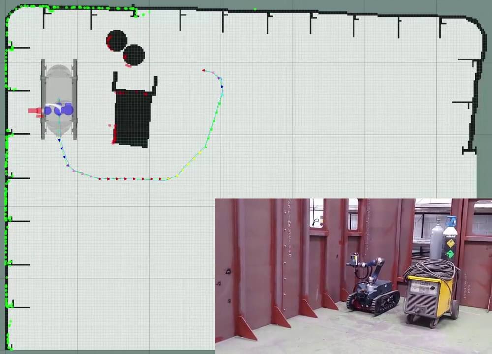
- Most of our mobile robots are equipped with two lidars (one in the front and another in the back), and as such, I developed the laserscan_to_pointcloud package that receives data from both lasers and creates a single point cloud with 360º laser data (the laserscan_to_pointcloud can be used for 1 or many lidars, and I implemented spherical linear interpolation for reducing the impact of scan deformation due to the robot motion during the sweep of the laser to retrieve the measurements)
In this video you can see the merged lidar data and its overlay on top of the 2D map after point cloud registration.
from dynamic_robot_localization.
 abylikhsanov
commented on May 18, 2024
abylikhsanov
commented on May 18, 2024
Thank for your detailed answer. I have read the paper about the different algorithm comparison. In your paper, you have shown your version of LUT-ICP. As I understand correctly, this is the version where you use the has table for 2d lidar instead of tree search? If so, where do you choose that specific algorithm in your 3 pose launch file?
from dynamic_robot_localization.
abylikhsanov
commented on May 18, 2024
Also, I guess ICP is not capable of global localization like particle filter?
from dynamic_robot_localization.
carlosmccosta
commented on May 18, 2024
For using the lookup table, you just need to go to the yaml files that specify the point matchers and add within their namespace (or parent namespace):
correspondence_estimation_approach: 'CorrespondenceEstimationLookupTable'
Then fine tune the lookup table parameters to your needs, such as, its cell resolution.
For example, if you use and configure the guardian_localization.launch to your use case, then just add within tracking_cluttered_environments_dynamic_large_map_2d.yaml/tracking_matchers the configurations I mentioned above.
This will activate the usage of the lookup tables when performing pose tracking.
If you also want the usage of lookup tables during the initial pose estimation and pose recovery, you just need to repeat the process for the yaml files associated, such as initial_pose_estimation_large_map_2d.yaml and tracking_recovery_2d.yaml.
Example of a testing yaml for 6 DoF available here.
Please be aware that the parameters are parsed according to the modules that are loaded dynamically, and their yaml hierarchy is described in drl_configs.yaml.
As such, you may see parameters for icp, ndt, gicp in the same level of the yaml, but notice that these will only be used if the corresponding algorithm is selected.
This allows me to quickly and easily switch between the different tracking algorithms, by just commenting / uncommenting the parent yaml level, as seen here, and then restart the launch file.
from dynamic_robot_localization.
carlosmccosta
commented on May 18, 2024
Point cloud registration algorithms such as ICP and NDT can achieve very accurate pose estimation but they require a rough initial alignment (otherwise it is unlikely that they will converge to the correct robot pose).
As such, the pipeline relies on feature matching for finding the initial pose of the robot on the map and then uses the efficient and accurate tracking algorithms for updating the robot pose as it moves.
The pipeline monitors the matching achieved by ICP or NDT and it can trigger the recovery algorithms for having a different set of algorithms (or same algorithms with different configurations) for recovering the tracking state, and if they fail, it will trigger the initial alignment algorithms for resetting the tracking by finding the global robot pose using feature matching.
You can find more detailed descriptions in this journal paper and my dissertation.
from dynamic_robot_localization.
abylikhsanov
commented on May 18, 2024
I just finished reading your dissertation and have a question about the
SLAM. So you would suggest to use the SLAM from your package as I can use
the spherical linear interpolation (causing the pointclouds to be less
noisy during the movement of a robot, especially during the pure rotation)?
Also, which localisation technique have you used for the SLAM? I am keen to
use ICP with hash tables (as I have a 2d lidar and embedded platform)
from dynamic_robot_localization.
carlosmccosta
commented on May 18, 2024
Good morning :)
The spherical linear interpolation is used in the laserscan_to_pointcloud package and relies on odometry to apply corrections to the laser scan data to mitigate deformations (that happen if you ignore the robot motion during the laser scan measurements acquisition -> lidars typically have 1 laser rotating at constant speed and taking measurements at specific time / angular intervals -> if the robot is also rotating, this will influence the measurement data because there will be an angular offset introduced by the robot motion -> you can see a few examples in the readme of the laserscan_to_pointcloud package).
In relation to slam (Simultaneous Localization And Mapping), the pipeline can operate in standalone mode or integrated with octomap.
The first point cloud is used as the initial reference map and then new laser scans are aligned to the slam map (that is built incrementally by merging new aligned laser scans).
The algorithm you use for alignment depends on your use case. But LUT-ICP for 2D lidars usually works well.
Also, the pipeline can be configured to use a set of filters for point cloud alignment and another set of filters (ambient_pointcloud_integration_filters) for generating the point cloud that will be used to incrementally build the map. This way, you can have fast alignment using a filtered point cloud with a low number of lidar measurements and then use for map update a point cloud with a high number of points.
If you already have a map, the pipeline allows to integrate into the map only new information (reference_pointcloud_update_mode: 'OutliersIntegration'). This is useful if you have an accurate map generated from CAD models or autocad drawings and want to add new information to the map (such as obstacles), while keeping the original map walls from being affected by the lidar noise (which will happen if you integrate into the map the full sensor data).
If there are dynamic objects in the scene, then the integration with octomap allows the usage of its raytracing implementation to detect if a set of voxels previously marked as occupied have became free in new sensor data (and should be removed from the map). This is a thin integration, in which I configured octomap to send to the drl node an updated map that replaces the one that drl is using for localization and mapping. This update is done after integrating a specified amount of point clouds.
Also, if you need a 2D occupancy grid, you will need octomap for generating it from the point cloud data.
I made some improvements to the octomap implementation, that are available in my forks:
But you can try using the official repositories.
Video showing a 2D slam example using drl:
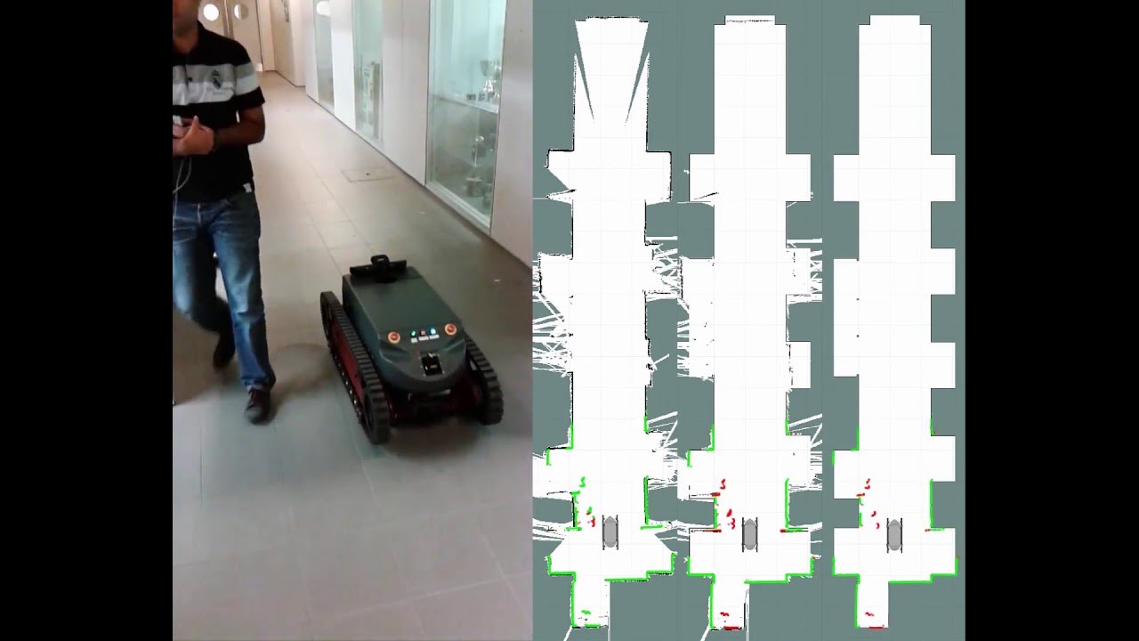
Left side: Mapping
Middle: Selective mapping with an initial world model
Right: Localization with a static world model
If you need mapping with loop closing optimization and besides lidar have a 2D camera, you can look at rtabmap.
from dynamic_robot_localization.
abylikhsanov
commented on May 18, 2024
Thank you. Also, do you the gazebo model with the noise implemented in
odometry and lidar data?
from dynamic_robot_localization.
abylikhsanov
commented on May 18, 2024
Sorry, I found it here:
https://github.com/inesc-tec-robotics/guardian_sim/blob/hydro-devel/guardian_description/urdf/guardian.gazebo
But not sure how you introduced the odometry gaussian noise though..
Also, comparing the simulation to the real world, from your dissertation,
you have shown the results for both and they did not differ that much, is
that because you have accurately introduced the noises via gazebo?
from dynamic_robot_localization.
carlosmccosta
commented on May 18, 2024
Good night :)
I configured the simulation of the lasers in gazebo to include gaussian noise (+- 1 cm).
The real odometry typically does not have a lot of noise (if good wheel encoders are used), instead, the most significant source of error is usually the wheel slippage, which introduces cumulative errors over time because both the real and simulated odometry is computed by looking at the amount of rotation of the wheels.
The slippage of the wheels in simulation happens easily, because tuning the friction coefficients of the wheels is tricky and the points of contact between the wheels and the environment estimated by the physics engine are not perfect.
The slippage along with the introduction of the gaussian noise in the laser data allowed to simulate +- the real robot, and that is why the robot localization results are similar, which is good
P.S.
Please do not responde using email, otherwise the previous replies get appended in your reply, which results in more scrolling on the github issue page to get to the new replies.
Thanks
I edited some of your replies to remove the repeated information.
Hope you don't mind :)
from dynamic_robot_localization.
abylikhsanov
commented on May 18, 2024
Hi, sure, not a problem, will use GitHub to reply directly :)
Regarding the sensors, what do you think of using two of these:
http://en.hypersen.com/product/detail/10.html
And making a 200 degree FoV?
from dynamic_robot_localization.
carlosmccosta
commented on May 18, 2024
The type of sensor depends on your use cases.
I haven't used those sensors from hypersen, but they seem good from the specs.
They have less FoV than most 2D lidars that usually have at least 180º and up to 360º.
However, these sensors from hypersen are solid state 3D lidars and are probably cheaper than 2D mechanical lidars.
For most of our AGVs that navigate in factory floors, we usually use 2D lidars from SICK due to safety requirements that demand hardware certified and able to stop the AGV when something enters its safety zone.
Robot localization and navigation from 2D lidars (3 DoF -> x,y,yaw) is also more robust (higher degrees of freedom -> 6 DoF, can significantly increase the search space for the point cloud registration algorithms, making them less reliable and requiring more computational resources to compute the robot pose).
Also 3D maps require more disk space.
from dynamic_robot_localization.
abylikhsanov
commented on May 18, 2024
Yes, I was thinking to use 3D Lidar as an obstacle detection but feed 2D data into your localization package (like simply picking the correct height from the data).
So if I combine two ToF sensors making a total of 200 degrees, do you think it is enough for the ICP localization?
from dynamic_robot_localization.
carlosmccosta
commented on May 18, 2024
It depends a lot on the environment in which the robot will be moving.
You can have 1 sensor seeing a corner and that would be enough for ICP.
Or could have 360º degrees FoV but be in corridor without seeing the end (which does not allow to restrict the dimension along the corridor direction) or be in the middle of a crowd and not being able to see the geometry associated with the localization map (these cases among others are not ideal for any map matching algorithm).
Overall, ICP can correctly converge if it can see enough distinctive geometry that allows to restrict the 3 DoF pose (such as corners).
For maximizing the robustness of the localization system, sensor data with large FoV and high range helps. But again, it depends on what are your use cases, budget and requirements relative to the robustness and accuracy of the localization system (which will influence what kind of sensors you need, how many and where are they placed).
from dynamic_robot_localization.
abylikhsanov
commented on May 18, 2024
Ok, and about the SLAM, I have noticed that you used Hector SLAM to create a map. Do you think having Hector map package is enough (without using the odometry) and then source its map to drl?
from dynamic_robot_localization.
carlosmccosta
commented on May 18, 2024
The drl can also do slam.
You have the flag use_slam in the guardian_localization.launch
But you can use any other slam system (hector, gmapping, ...) or even generate the map from CAD models.
For drl it only matters if the map is accurate and representative of the environment.
from dynamic_robot_localization.
Related Issues (20)
- How do you get the correct TF? HOT 1
- the angle unit HOT 1
- 2-D global (3 DoF) localization questions HOT 21
- Using sparse and noisy PointCloud2 HOT 1
- build with ros-noetic HOT 2
- ROS2 Support HOT 2
- How to use 6 DoF robot localization HOT 11
- Selecting RoI HOT 1
- HSVto RGB HOT 1
- Lidar in pointcloud localization HOT 9
- Node doesn't start due to invalid time? HOT 1
- Mismatch between 6DoF tracking achieved locally and the reference video with same data set HOT 2
- Initial pose and odometry reuse HOT 6
- Turn on/off the tracking HOT 1
- compile errors HOT 9
- **[URGENT]** What is the result of the 3dof localization? HOT 11
- localization result unstable HOT 1
- 2D localization mode have roll pitch and Zaxis drit HOT 14
- Pointclouds get dropped HOT 3
- error:registration.registerVisualizationCallback(this->update_visualizer_); HOT 5
Recommend Projects
-
 React
React
A declarative, efficient, and flexible JavaScript library for building user interfaces.
-
Vue.js
🖖 Vue.js is a progressive, incrementally-adoptable JavaScript framework for building UI on the web.
-
 Typescript
TypeScript is a superset of JavaScript that compiles to clean JavaScript output.
-
TensorFlow
An Open Source Machine Learning Framework for Everyone
-
Django
The Web framework for perfectionists with deadlines.
-
 Laravel
A PHP framework for web artisans
-
D3
Bring data to life with SVG, Canvas and HTML. 📊📈🎉
-
Recommend Topics
-
javascript
JavaScript (JS) is a lightweight interpreted programming language with first-class functions.
-
web
Some thing interesting about web. New door for the world.
-
server
A server is a program made to process requests and deliver data to clients.
-
Machine learning
Machine learning is a way of modeling and interpreting data that allows a piece of software to respond intelligently.
-
Visualization
Some thing interesting about visualization, use data art
-
Game
Some thing interesting about game, make everyone happy.
Recommend Org
-
Facebook
We are working to build community through open source technology. NB: members must have two-factor auth.
-
Microsoft
Open source projects and samples from Microsoft.
-
Google
Google ❤️ Open Source for everyone.
-
Alibaba
Alibaba Open Source for everyone
-
D3
Data-Driven Documents codes.
-
Tencent
China tencent open source team.
from dynamic_robot_localization.